Magnetic multilayer film, memory unit and memory

A storage unit and multi-layer film technology, applied in the field of magnetic field controlled resistors, electrical components, semiconductor devices, etc., can solve the problem of thermal stability factor Δ reduction, achieve high thermal stability factor, comprehensive performance improvement, and low turnover The effect of current

Pending Publication Date: 2022-05-06
ZHEJIANG HIKSTOR TECHOGY CO LTD
View PDF0 Cites 0 Cited by
  • Summary
  • Abstract
  • Description
  • Claims
  • Application Information

AI Technical Summary

Problems solved by technology

[0005] The main purpose of the present invention is to provide a magnetic multilayer film, storage unit and memory, to solve the problem that the method of reducing the write current of the MTJ device in the prior art will simultaneously lead to a significant reduction in the thermal stability factor Δ

Method used


Image

  • Magnetic multilayer film, memory unit and memory
  • Magnetic multilayer film, memory unit and memory
  • Magnetic multilayer film, memory unit and memory

Examples


Embodiment 1

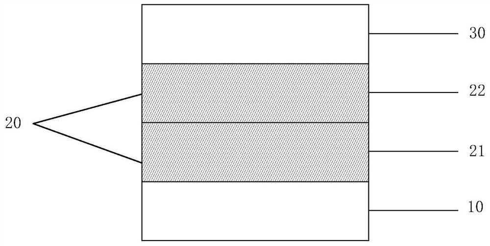
[0042] figure 1 The shown free layer includes a first magnetic layer 10 , a spacer film 20 (including a first spacer sub-film 21 , a second spacer sub-film 22 ) and a second magnetic layer 30 deposited in sequence. Wherein the first magnetic layer 10 and the second magnetic layer 30 are Co 20 Fe 55 B 25 The alloy has a thickness of 1 nm; the first spacer film 21 is W with a thickness of 0.3 nm; the second spacer film 22 is Mg with a thickness of 0.2 nm.

Embodiment 2

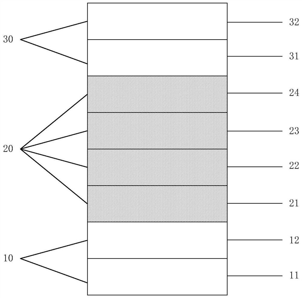
[0044] figure 2 The shown free layer includes a first magnetic layer 10 (comprising a first sub-magnetic layer 11 and a second sub-magnetic layer 12), a spacer film 20 (comprising a first spacer sub-film 21, a second spacer sub-film 22, the third spacer sub-film 23 , the fourth spacer sub-film 24 ) and the second magnetic layer 30 (including the third sub-magnetic layer 31 and the fourth sub-magnetic layer 32 ). Wherein the first sub-magnetic layer 11 is CoFe with a thickness of 0.5nm; the second sub-magnetic layer 12 is Co 20 Fe 60 B 20 Alloy with a thickness of 0.7nm; the first spacer film 21 is Al with a thickness of 0.2nm; the second spacer film 22 is Hf with a thickness of 0.3nm; the third spacer film 23 is Mg with a thickness of 0.2nm; The four-spacer film 24 is Mo with a thickness of 0.1nm; the third sub-magnetic layer 31 is Co 20 Fe 60 B 20 alloy, the thickness of which is 0.5nm; the fourth sub-magnetic layer 32 is Co 40 Fe 40 B 20 alloy with a thickness of 0...

Embodiment 3

[0046] The free layer includes a first magnetic layer (including a first sub-magnetic layer and a second sub-magnetic layer), a spacer film (including a first spacer sub-film, a second spacer sub-film, a third spacer sub-film) and a second spacer film deposited in sequence. Magnetic layers (including the third sub-magnetic layer, the fourth sub-magnetic layer and the fifth sub-magnetic layer). The first sub-magnetic layer is Co with a thickness of 0.4nm; the second sub-magnetic layer is Fe 80 B 20 , the thickness is 0.8nm; the first spacer film is Al, the thickness is 0.1nm; the second spacer film is Mo, the thickness is 0.3nm; the third spacer film is Mg, the thickness is 0.2nm; the third sub-magnetic layer It is CoFe with a thickness of 0.5nm; the fourth sub-magnetic layer is Co 30 Fe 50 B 20 , with a thickness of 0.3nm; the fifth sub-magnetic layer is Co 20 Fe 60 B 20 , with a thickness of 0.3nm.


PUM

PropertyMeasurementUnit
thicknessaaaaaaaaaa
thicknessaaaaaaaaaa
thicknessaaaaaaaaaa

Abstract

The invention provides a magnetic multilayer film, a memory cell and a memory. The magnetic multilayer film comprises a first magnetic layer, a spacing film and a second magnetic layer which are sequentially stacked in the first stacking direction, the spacing film comprises multiple layers of spacer films stacked in the second stacking direction, the first stacking direction and the second stacking direction are the same, and at least one layer in the spacer films is a non-magnetic spacer film. The multi-layer spacer film is arranged, on one hand, it is guaranteed that the magnetic multi-layer film has high perpendicular magnetic anisotropy (PMA), and the expected magnetization direction is obtained when the magnetic multi-layer film is used as a free layer of the magnetic tunnel junction. And on the other hand, the magnetic layers on the two sides of the multi-layer spacer film can realize relatively strong interlayer magnetic coupling, so that the magnetization directions of the magnetic layers can be turned over simultaneously under the action of a relatively small external magnetic field or impressed current. When the magnetic multilayer film is used as a free layer of a magnetic tunnel junction, the MTJ device with the free layer can realize a high thermal stability factor delta and a low flip current.

Description

technical field [0001] The invention relates to the field of magnetic random access memory, in particular to a magnetic multilayer film, a storage unit and a memory. Background technique [0002] The magnetic random access memory (MRAM) is composed of a magnetic tunnel junction (MTJ) array, and the core structure of the MTJ includes a free layer, a barrier layer and a pinned layer. Among them, the free layer and the fixed layer are magnetic layers, and the barrier layer is a very thin insulating layer, generally less than 3nm in thickness. When the MTJ works normally, the magnetization direction of the fixed layer remains unchanged, and the magnetization direction of the free layer can be changed by an external magnetic field or input current. The resistance value of the MTJ is determined by the relative magnetization directions of the free layer and the fixed layer. When the magnetization direction of the free layer is parallel to the fixed layer, the MTJ is in a low-resis...

Claims


Application Information

Patent Timeline
Patent Type & Authority Applications(China)
IPC IPC(8): H01L43/02H01L43/08H01L43/10H01L43/12H01L27/22
CPCH10B61/00H10N50/80H10N50/85H10N50/10H10N50/01
Inventor 宫俊录孟凡涛孙一慧简红
Owner ZHEJIANG HIKSTOR TECHOGY CO LTD
Why Eureka
Try Eureka