Heat dissipation oil storage bin of hydraulic plate shearing machine

An oil storage bin and hydraulic shearing technology, applied in shearing devices, shearing machine equipment, accessories of shearing machines, etc., can solve problems such as affecting the service life of the equipment and poor heat dissipation effect, reducing volume and improving heat dissipation. The effect of exchange area and easy discharge

Active Publication Date: 2022-05-10
江苏新益机械有限公司
View PDF9 Cites 0 Cited by
  • Summary
  • Abstract
  • Description
  • Claims
  • Application Information

AI Technical Summary

Problems solved by technology

The oil storage tanks for hydraulic shearing machines in the prior art are generally hidden inside the equipment, and the heat dissipation effect is not good, which affects the service life of the equipment

Method used


Image

  • Heat dissipation oil storage bin of hydraulic plate shearing machine
  • Heat dissipation oil storage bin of hydraulic plate shearing machine
  • Heat dissipation oil storage bin of hydraulic plate shearing machine

Examples


Embodiment 1

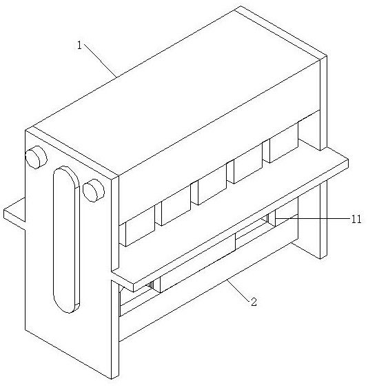
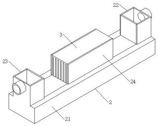
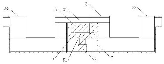
[0028] As shown in 1-2, the present invention is a heat dissipation oil storage bin of a hydraulic shearing machine, including a shearing machine 1, an oil storage bin is installed at the bottom of the shearing machine 1, and the oil storage bin includes a channel 2, fins 3 and The sealing block 7, the channel 2 includes a pipe body 21, an oil inlet opening 22 and an oil outlet opening 23, and the two ends of the pipe body 21 are respectively connected with the oil inlet opening 22 and the oil outlet opening 23; the middle part of the pipe body 21 is sealed with a sealing block 7. The bottom surface of the pipe body 21 and the opening groove 71 provided in the sealing block 7 form an oil passage; road.

[0029] An air passage is formed between the inner side of the provided fin 3 and the outer surface of the sealing block 7, the bottom surface of the pipe body 21 and the opening groove 71 provided in the sealing block 7 form an oil passage, and the air passage and the oil pass...

Embodiment 2

[0031] As shown in 3-5, the present invention is a heat dissipation oil storage bin for a hydraulic shearing machine, including a shearing machine 1, an oil storage bin is installed at the bottom of the shearing machine 1, and the oil storage bin includes a channel 2, fins 3 and The sealing block 7, the channel 2 includes a pipe body 21, an oil inlet opening 22 and an oil outlet opening 23, and the two ends of the pipe body 21 are respectively connected with the oil inlet opening 22 and the oil outlet opening 23; the middle part of the pipe body 21 is sealed with a sealing block 7. The bottom surface of the pipe body 21 and the opening groove 71 provided in the sealing block 7 form an oil passage; road.

[0032] An air passage is formed between the inner side of the provided fin 3 and the outer surface of the sealing block 7, the bottom surface of the pipe body 21 and the opening groove 71 provided in the sealing block 7 form an oil passage, and the air passage and the oil pas...


PUM


Abstract

The invention discloses a heat dissipation oil storage bin of a hydraulic plate shearing machine, and relates to the technical field of plate shearing machine assemblies. The plate shearing device comprises a plate shearing machine, an oil storage bin is installed at the bottom of the plate shearing machine, the oil storage bin comprises a channel, fins and a sealing block, the channel comprises a pipe body, an oil inlet and an oil outlet, and the two ends of the pipe body communicate with the oil inlet and the oil outlet correspondingly; a sealing block is installed in the middle of the pipe body in a sealing mode, and the bottom face of the pipe body and an opening groove formed in the sealing block form an oil channel. Fins are installed on the outer sides of the sealing blocks, and air channels are formed between the inner sides of the fins and the outer side faces of the sealing blocks. External air flows through the air duct through the vent groove and exchanges heat with oil passing through the oil channel, so that hydraulic oil is cooled.

Description

technical field [0001] The invention belongs to the technical field of shearing machine components, and in particular relates to a heat dissipation oil storage bin of a hydraulic shearing machine. Background technique [0002] The shearing machine uses the moving upper blade and the fixed lower blade to apply shearing force to metal sheets of various thicknesses with a reasonable blade gap, so that the sheets are broken and separated according to the required size. The shearing machine is a kind of forging machinery, and its main function is the metal processing industry. With the rapid development of the machinery industry, the shearing machine has developed from the original mechanical transmission to hydraulic transmission. The temperature of the oil in hydraulic transmission is generally controlled at about 60°C-80°C, and the maximum should not exceed 85°C. If the oil temperature is too high, the hydraulic system will have the following adverse effects: (1) The viscosit...

Claims


Application Information

Patent Timeline
Patent Type & Authority Applications(China)
IPC IPC(8): B23D15/14B23D15/08B23D33/00
CPCB23D15/14B23D15/08B23D33/00Y02P70/10
Inventor 储伯生
Owner 江苏新益机械有限公司
Why Eureka
Try Eureka