
Automatic shearing intelligent manufacturing equipment for metal bar polishing machining

A technology of intelligent manufacturing and metal bar, applied in the field of metal bar, can solve the problems of relatively many steps, complicated operation, heat generation, etc., to improve the use efficiency, ensure the accuracy, and avoid accidental injury.

Pending Publication Date: 2022-05-10
蒋学财
View PDF0 Cites 0 Cited by
  • Summary
  • Abstract
  • Description
  • Claims
  • Application Information

AI Technical Summary

Problems solved by technology

[0003] However, in the traditional manual polishing machine equipment, it is common for people to hold an iron rod close to the throwing plate. However, it will be very sore after a long time of operation. When the iron rod is close, it may be brought in due to the excessive speed of rotation. At the same time, the iron rod will generate more heat after a long time, and it is easy to burn the skin. Not only that, but most of the iron rods often need to be sheared after processing. None of them have the function of simultaneous shearing, relatively more steps, and more cumbersome operation, so an intelligent manufacturing equipment for automatic shearing of metal rod polishing came into being

Method used


Image

  • Automatic shearing intelligent manufacturing equipment for metal bar polishing machining
  • Automatic shearing intelligent manufacturing equipment for metal bar polishing machining
  • Automatic shearing intelligent manufacturing equipment for metal bar polishing machining

Examples

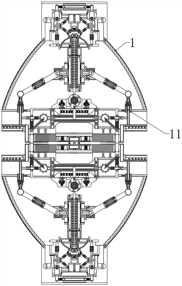
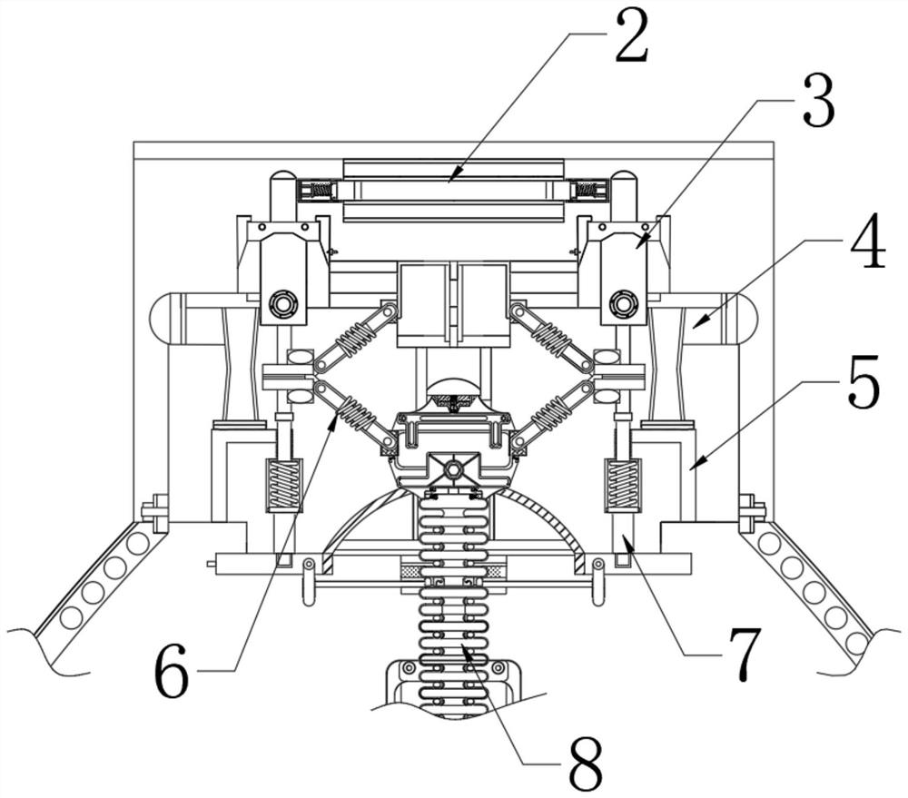
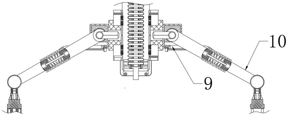

Embodiment Construction

[0025] The following will clearly and completely describe the technical solutions in the embodiments of the present invention with reference to the accompanying drawings in the embodiments of the present invention. Obviously, the described embodiments are only some, not all, embodiments of the present invention. Based on the embodiments of the present invention, all other embodiments obtained by persons of ordinary skill in the art without making creative efforts belong to the protection scope of the present invention.

[0026] see Figure 1-5 :

[0027] An intelligent manufacturing equipment for automatic shearing of metal rod polishing, including a main body 1, the top of the main body 1 is movably connected to a driving part 2 located in the middle of an action block 3, and the lower end of the driving part 2 is movably connected to a function above a limit bar 4 Block 3, this structure has stability and ease of use; the top of the main body 1 is movably connected to the d...


PUM


Abstract

The invention relates to the technical field of metal bars, and discloses automatic-shearing intelligent manufacturing equipment for metal bar polishing, which comprises a main body, and the top end of the main body is movably connected with a driving part. According to the automatic-shearing intelligent manufacturing equipment for metal rod polishing machining, when a main shaft is pressed downwards to move along a groove in a rail, centrifugal force generated by rotating and pressing the main shaft can attract core strips at the two ends to move towards the middle, the core strips slowly move in the direction close to the rail, and when an abutting plate moves, a nylon rope in the abutting plate can be pulled to move; when the main shaft and a workpiece are polished for a certain time according to an expected program, the tool bit at the top end of the core strip is gradually inserted into the main shaft to quantitatively shear the main shaft, so that the equipment has an automatic shearing function, and meanwhile, the situation that people are easily injured due to high temperature is also avoided; many steps are relatively reduced, and the operation is simpler and quicker.

Description

technical field [0001] The invention relates to the technical field of metal rods, in particular to an intelligent manufacturing equipment for automatic shearing of metal rods for polishing. Background technique [0002] The polishing machine is also called a grinding machine. It is often used as a mechanical grinding, polishing, waxing, and manual polishing machine. Its working principle is: the motor drives the sponge or wool polishing disc installed on the polishing machine to rotate at a high speed. Work together and rub against the surface to be polished, and then achieve the purpose of removing paint surface pollution, oxide layer, and shallow marks. The polishing machine provides people with a lot of convenience. [0003] However, in the traditional manual polishing machine equipment, it is common for people to hold an iron rod close to the throwing plate. However, it will be very sore after a long time of operation. When the iron rod is close, it may be brought in d...

Claims


Application Information

Patent Timeline
Patent Type & Authority Applications(China)
IPC IPC(8): B23P23/04
CPCB23P23/04
Inventor 蒋学财
Owner 蒋学财
Learn More