Workbench for industrial robot manufacturing part machining

An industrial robot and parts processing technology, which is applied to metal processing machinery parts, manufacturing tools, metal processing equipment, etc., can solve the problems of increased debugging time, impracticality, and poor convenience, and achieve the effect of reducing workload and high efficiency

Active Publication Date: 2022-05-10
厦门工学院
View PDF8 Cites 0 Cited by
  • Summary
  • Abstract
  • Description
  • Claims
  • Application Information

AI Technical Summary

Problems solved by technology

The existing workbench for robot manufacturing parts processing has a simple structure and consists of a worktable and table legs. When installing parts, the worktable cannot be moved or rotated. It is not only inconvenient to install workpieces of various types and sizes, especially It is necessary to install large-sized workpieces, and when processing multiple parts on large-sized workpieces, either choose to move the workpiece or increase the number of clamping times of the workpiece, which will greatly increase the workload and strength of the staff, poor convenience, or increase The number of robot job programming makes the robot program programming more complicated, which increases the debugging time and greatly affects the work efficiency; at the same time, it is very inconvenient to load and unload only on one side of the table, and it is not suitable for loading and unloading on complex construction sites. material
In addition, this workbench has no chip collecting parts. Relying on manual cleaning alone is not only time-consuming and labor-intensive, but also goes against the original intention of using industrial robots to reduce the workload of the staff. At the same time, during the cleaning process, it also affects the installation of subsequent parts that need to be processed. , increasing the production cycle, very impractical and unreliable

Method used


Image

  • Workbench for industrial robot manufacturing part machining
  • Workbench for industrial robot manufacturing part machining
  • Workbench for industrial robot manufacturing part machining

Examples


Embodiment Construction

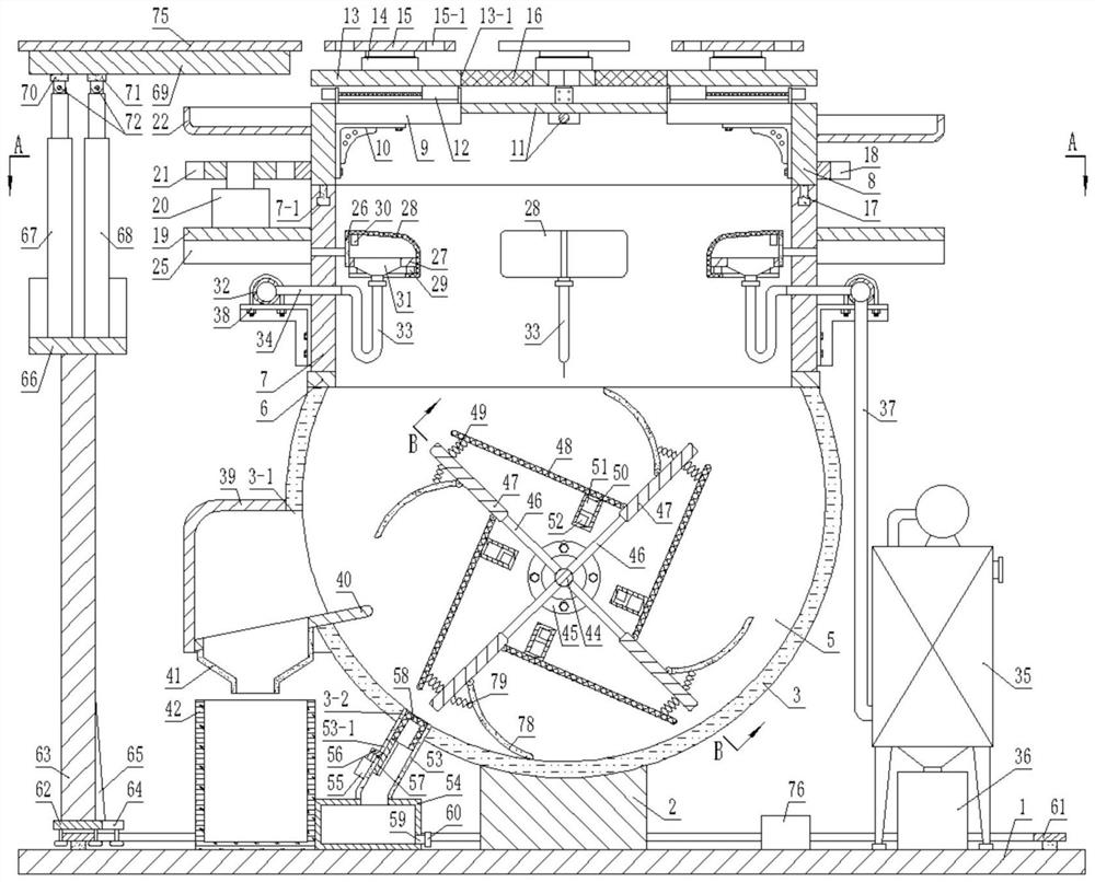
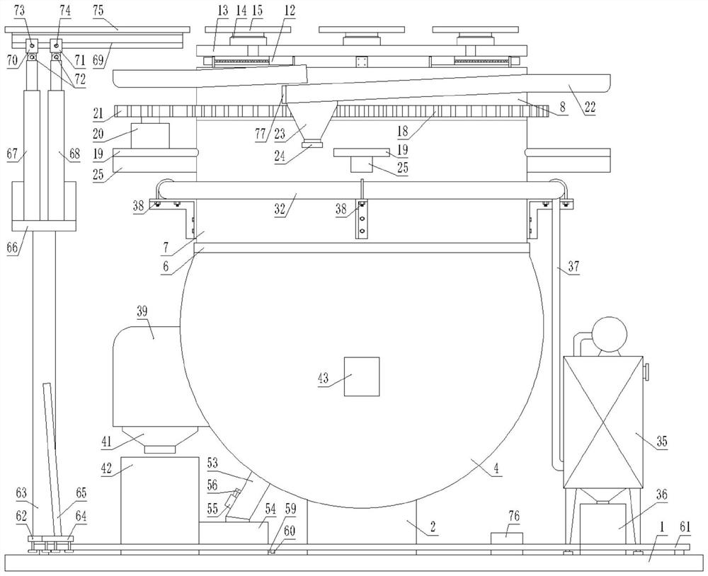
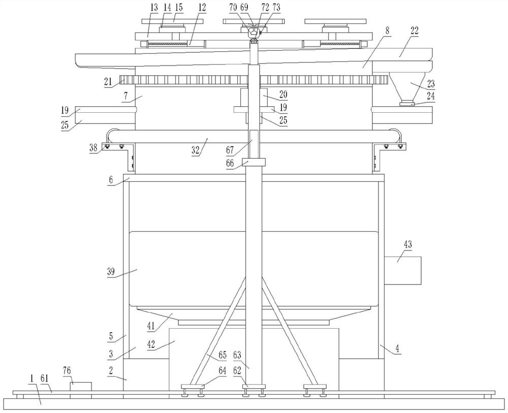
[0022] Below in conjunction with accompanying drawing and specific embodiment the present invention is described in further detail:

[0023] Such as Figure 1-Figure 10 As shown, a workbench for industrial robot manufacturing parts processing includes a base plate 1, a support base 2 is fixed in the middle of the top surface of the base plate 1, and an arc-shaped groove 3 is fixedly installed on the top surface of the support base 2. The two ends of arc-shaped groove 3 are respectively sealed and fixed with matching front cover plate 4 and rear cover plate 5, and the top surface of described arc-shaped groove 3 is sealed and fixed with matching upper cover plate 6, and the upper cover The top surface of the plate 6 is penetrated and fixed with a first circular cylinder 7, the top surface of the first circular cylinder 7 is provided with an annular chute 7-1, and multiple sliding grooves are arranged in the annular chute 7-1 A first slide block 17 matching it, the top surface ...


PUM


Abstract

The invention discloses an industrial robot manufacturing part machining workbench which comprises a bottom plate, a supporting seat is fixed to the middle of the top face of the bottom plate, an arc-shaped groove is fixedly formed in the top face of the supporting seat, and a front cover plate and a rear cover plate matched with the arc-shaped groove are fixed to the two ends of the arc-shaped groove in a sealed mode correspondingly. An upper cover plate is hermetically fixed on the top surface of the arc-shaped groove. The feeding device is provided with the feeding plate, practical, convenient and suitable for feeding and discharging in a complex construction site, the hydraulic rotary table, the electric sliding table, the gear, the outer gear ring and other components are arranged below the workbench, any position and angle of a workpiece on the movable workbench can be adjusted, the machining positions of the installed workpieces of different types can be adjusted conveniently, and the machining efficiency is improved. Workpieces of various types and sizes are convenient to install, the use efficiency is high, dust, slag and waste water generated during construction can be cleaned and collected through work of a dust remover, a second motor, an air cylinder and other components, the workload of workers is reduced, time and labor are saved, and the device is very practical and reliable.

Description

technical field [0001] The invention relates to the field of machinery, in particular to a workbench for manufacturing and processing industrial robot parts. Background technique [0002] Industrial robots are multi-joint manipulators or multi-degree-of-freedom machine devices for the industrial field. With the development of industry, industrial robots can replace people to complete complicated and monotonous repetitive work, and work in harmful, toxic, high-temperature and other harsh environments. . The existing workbench for robot manufacturing parts processing has a simple structure and consists of a worktable and table legs. When installing parts, the worktable cannot be moved or rotated. It is not only inconvenient to install workpieces of various types and sizes, especially It is necessary to install large-sized workpieces, and when processing multiple parts on large-sized workpieces, either choose to move the workpiece or increase the number of clamping times of th...

Claims


Application Information

Patent Timeline
Patent Type & Authority Applications(China)
IPC IPC(8): B23Q1/26B23Q11/00
CPCB23Q1/26B23Q11/0046
Inventor 徐彩莲林舜美
Owner 厦门工学院
Why Eureka
Try Eureka