Pulsating gas generating device and unstable combustion experimental equipment
A technology of gas generating device and experimental equipment, which is applied to jet propulsion devices, rocket engine devices, mechanical equipment, etc., can solve problems such as explosion, shortened engine life, and damage to engine components, and achieve good experimental results, simple structure, and convenient installation Effect
- Summary
- Abstract
- Description
- Claims
- Application Information
AI Technical Summary
Problems solved by technology
Method used
Image
Examples
Embodiment 1
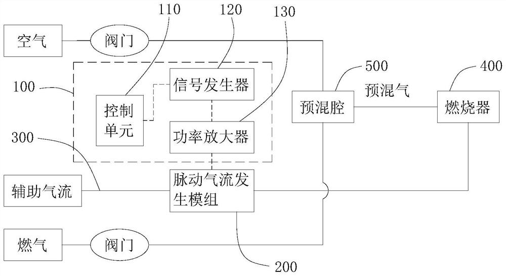
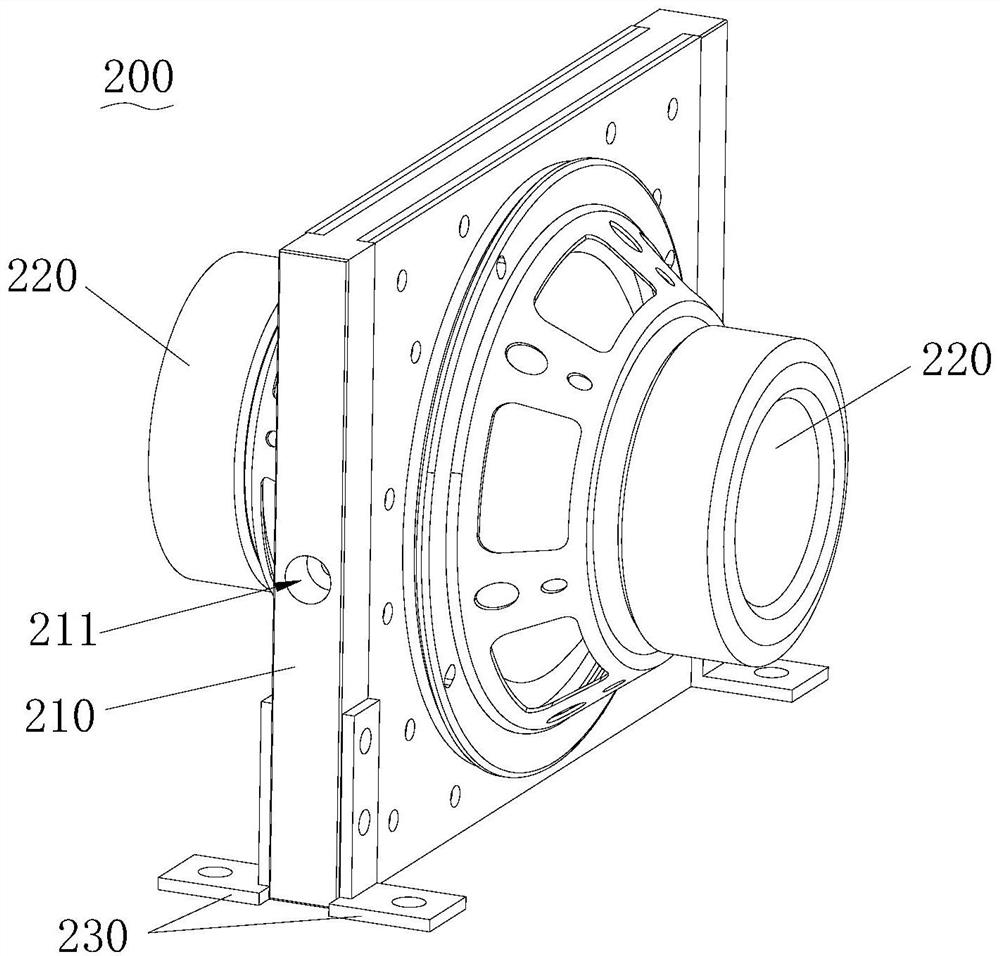
[0042] see figure 1 , figure 2 and image 3 , this embodiment provides a pulsating gas generating device, which is applied to unstable combustion experimental equipment and used for research on unstable combustion experiments. Wherein, the unstable combustion experimental equipment includes a rocket engine model combustion chamber, and the rocket engine model combustion chamber has a premix chamber 500 and a burner 400 .
[0043] In this implementation, the pulsating gas generating device includes a control module 100 and a pulsating airflow generating module 200 , the control module 100 and the pulsating airflow generating module 200 are electrically connected to control the pulsating airflow generating module 200 to operate.
[0044] Please also refer to Figure 6 Specifically, the control module 100 includes a control unit 110 , a signal generator 120 and a power amplifier 130 that are electrically connected in sequence. The pulsating airflow generation module 200 incl...
Embodiment 2
[0071] see Figure 6 and Figure 9 , this embodiment provides a pulsating gas generating device, which is applied to unstable combustion experimental equipment and used for research on unstable combustion.
[0072] In this embodiment, the base 210 includes a seat body 210a, two mounting plates 210b, and a plurality of adjusting components 210d. Wherein, the seat body 210a is provided with a cavity 212, and the seat body 210a is provided with an air inlet 211 and an air outlet 213 communicating with the cavity 212, wherein, the design scheme of the cavity 212, the air inlet 211 and the air outlet 213 Continue to use the solution in the first implementation above, and will not repeat it in detail in this embodiment.
[0073] Further, the two mounting plates 210b are respectively arranged on both sides of the base body 210a, and the mounting plate 210b and the base body 210a are sealed and connected by a retractable bellows 210c, and the two mounting plates 210b are away from t...
PUM
 Abstract
Description
Claims
Application Information
 - R&D
- Intellectual Property
- Life Sciences
- Materials
- Tech Scout
- Unparalleled Data Quality
- Higher Quality Content
- 60% Fewer Hallucinations
Browse by: Latest US Patents, China's latest patents, Technical Efficacy Thesaurus, Application Domain, Technology Topic, Popular Technical Reports.
© 2025 PatSnap. All rights reserved.Legal|Privacy policy|Modern Slavery Act Transparency Statement|Sitemap|About US| Contact US: help@patsnap.com


