Optical module, insertion core and optical fiber connector

An optical fiber connector and optical module technology, applied in the field of optical communication, can solve problems such as conflicts, single-fiber bidirectional optical modules cannot meet the expansion capacity, single-fiber bidirectional optical modules cannot be applied, etc., to achieve the effect of satisfying system capacity expansion

Pending Publication Date: 2022-05-10
HUAWEI TECH CO LTD
View PDF11 Cites 1 Cited by
  • Summary
  • Abstract
  • Description
  • Claims
  • Application Information

AI Technical Summary

Problems solved by technology

like image 3 As shown, when the single-fiber bidirectional optical module is applied to the communication between the baseband processing unit (baseband unit, BBU) and the active antenna unit (active antenna unit, AAU), it may appear that the multiplexer and demultiplexer receive through fiber #1 at the same time The optical signal and the situation of sending the optical signal cause conflicts. Therefore, the single-fiber bidirectional optical module cannot be applied to the scene directly connected to the multiplexer / demultiplexer
In addition, if the communication system needs to expand to a larger capacity, the single-fiber bidirectional optical module may not be able to meet the demand for capacity expansion

Method used


Image

  • Optical module, insertion core and optical fiber connector
  • Optical module, insertion core and optical fiber connector
  • Optical module, insertion core and optical fiber connector

Examples


Embodiment Construction

[0046] The technical solutions in the embodiments of the present application will be described below with reference to the accompanying drawings.

[0047] The technical solution of the embodiment of the present application can be applied to various communication systems, for example: a 4th generation (4thgeneration, 4G) system, such as a long term evolution (long term evolution, LTE) system, a 5th generation (5thgeneration, 5G) system, such as New radio (new radio, NR), or other communication systems that may appear in the future, etc.

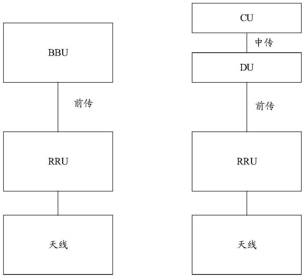
[0048] In the above communication system, a base station can communicate with one or more terminals. The base station may include one or more baseband modules, one or more radio frequency modules, and one or more antennas, through the one or more baseband modules, the one or more radio frequency modules, and the one or more antennas, the base station Communication with one or more terminals can be realized.

[0049] Wherein, the baseband mod...


PUM


Abstract

According to the optical module, the insertion core and the optical fiber connector provided by the embodiment of the invention, a plurality of optical signals can be transmitted through one optical interface, so that the optical module meets the requirement of system capacity expansion. The optical module comprises N optical units, a wave division unit and an optical fiber connector, the optical fiber connector comprises an insertion core and M optical fibers, the M optical fibers are arranged in the insertion core, each optical fiber in the M optical fibers corresponds to at least one optical unit in the N optical units, and the optical units corresponding to any two optical fibers in the M optical fibers are different; m is an integer greater than or equal to 2, and N is an integer greater than or equal to M; the first optical fiber is used for transmitting an optical signal received by the optical unit corresponding to the first optical fiber, and/or is used for transmitting an optical signal received by the optical unit corresponding to the first optical fiber, and the first optical fiber is any one of the M optical fibers.

Description

technical field [0001] The embodiments of the present application relate to the technical field of optical communication, and more specifically, relate to an optical module, a ferrule, and an optical fiber connector. Background technique [0002] With the advancement of information technology and the needs of network applications, single-fiber bidirectional optical modules are widely used in communication networks because they can save one fiber resource and improve the capacity of communication systems compared with traditional dual-fiber bidirectional optical modules. . like image 3 As shown, when the single-fiber bidirectional optical module is applied to the communication between the baseband processing unit (baseband unit, BBU) and the active antenna unit (active antenna unit, AAU), it may appear that the multiplexer and demultiplexer receive through fiber #1 at the same time The optical signal and the situation of sending the optical signal cause conflicts. Therefore...

Claims


Application Information

Patent Timeline
Patent Type & Authority Applications(China)
IPC IPC(8): G02B6/38G02B6/42
CPCG02B6/3807G02B6/3833G02B6/424
Inventor 黄鑫华兰鹏冯佳李惠萍
Owner HUAWEI TECH CO LTD
Why Eureka
Try Eureka