Impulse current grounding device and method

An inrush current and grounding device technology, applied in the direction of connecting contact materials, etc., can solve problems such as failure to meet grounding requirements, abnormal insulation of equipment, measurement interference, etc., and achieve the effect of reducing grounding inductance, ensuring normal operation, and reducing interference.

Active Publication Date: 2022-05-10
NORTHWEST INST OF NUCLEAR TECH
View PDF12 Cites 0 Cited by
  • Summary
  • Abstract
  • Description
  • Claims
  • Application Information

AI Technical Summary

Problems solved by technology

[0005] The purpose of the present invention is to solve the technical problems that the existing grounding device and method cannot meet the grounding requirements of hundreds of ns and several kA impulse currents generated on the shell of the pulse power device at the moment of operation, resulting in measurement interference, equipment abnormality or insulation breakdown, and provides An impulse current grounding device and method, which can reduce the grounding inductance, impact grounding resistance and grounding point impulse voltage of a pulse power device, thereby reducing interference, protecting the pulse power device and various electrical systems, and improving the operating voltage level of the pulse power device , to ensure the stable operation of the pulse power device

Method used


Image

  • Impulse current grounding device and method
  • Impulse current grounding device and method
  • Impulse current grounding device and method

Examples


Embodiment Construction

[0058] The technical solutions of the present invention will be clearly and completely described below in conjunction with the accompanying drawings. Apparently, the described embodiments are some of the embodiments of the present invention, but not all of them. Based on the embodiments of the present invention, all other embodiments obtained by persons of ordinary skill in the art without making creative efforts belong to the protection scope of the present invention.

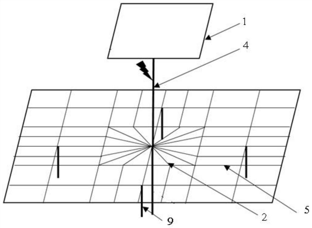
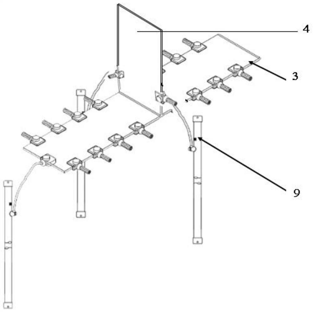
[0059] Such as figure 1 As shown, an impulse current grounding device includes a grounding body buried in the ground. The grounding body includes a down-conducting plate, a grounding grid arranged under the down-conducting plate, and multiple grounding electrodes; 1 and is connected to the pulse power device shell 1, leading the impact current of a specific leading edge into the radiation network;

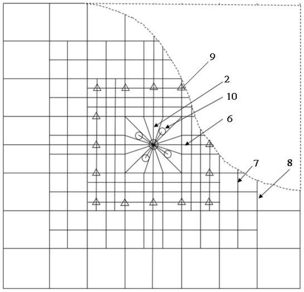
[0060] The grounding grid is provided with a radiation grid and a horizontal grounding grid 5 arranged around t...


PUM


Abstract

The invention relates to pulse power device grounding, in particular to an impulse current grounding device and method, and solves the technical problems of measurement interference, equipment abnormity or insulation breakdown caused by the fact that an existing grounding device and method cannot meet the grounding requirements of hundreds of ns and several kA impulse currents generated on a shell at the moment that a pulse power device works. The impulse current grounding device comprises a buried grounding body, a leading-down plate, a grounding grid arranged below the leading-down plate and a plurality of grounding electrodes arranged below the grounding grid. The leading-down plate is used for leading impact current at a specific front edge into the radiation net; the grounding grid comprises a radiation grid, a horizontal grounding grid arranged around the radiation grid and a plurality of grounding electrodes; the radiation net comprises m radiation leads which are radially distributed, m is greater than or equal to 4, and the grounding electrode is arranged below the horizontal grounding net; grounding inductance and impact grounding resistance of the pulse power device are reduced, impact voltage of a grounding point is reduced, interference is reduced, and the pulse power device is protected.

Description

technical field [0001] The invention relates to the grounding of pulse power devices, in particular to a surge current grounding device and method. Background technique [0002] With the rapid development of pulse power technology in recent years, pulse power devices show the characteristics of high power, large devices, and multiple parallel operation, and the output voltage and current of the devices are gradually increased. For example, the "Shenlong No. "The highest voltage can reach 20MV, the current of "Julong No. 1" used for Z-pinch research can reach 10MA, and the electric power level can reach 10TW (Cong Peitian, Brief introduction to the progress of pulse power technology in China[J]. Strong laser and particle beam, 2020, 32(2): 025002-1-11). When this type of large-scale pulse power device is running, due to factors such as stray capacitance and switch discharge, instantaneous high voltage will be induced on the device, causing damage to the power supply system, ...

Claims


Application Information

Patent Timeline
Patent Type & Authority Applications(China)
IPC IPC(8): H01R4/66H01R4/58
CPCH01R4/66H01R4/58
Inventor 周文渊丛培天张新彪呼义翔郭晓强孙剑锋
Owner NORTHWEST INST OF NUCLEAR TECH
Why Eureka
Try Eureka