Pin position arrangement method of hybrid power supply connector

A hybrid power supply and connector technology, applied in connection, circuit/collector parts, circuits, etc., can solve problems such as single connector, research on the arrangement of signal lines and power lines of hybrid power supply connectors, etc. Effectiveness of utilization and prevention of eye fatigue

Pending Publication Date: 2022-05-10
GOLDENCONN ELECTRONICS TECH CO LTD
View PDF0 Cites 0 Cited by
  • Summary
  • Abstract
  • Description
  • Claims
  • Application Information

AI Technical Summary

Problems solved by technology

[0002] There are power lines and signal lines in the hybrid power connector, so that both signal transmission and power transmission can be carried out, but since the current connectors are all single, either for power transmission or for signal transmission, therefore, There is no research on the number and arrangement of signal lines and power lines inside the hybrid power connector, but the power connector needs to adapt to the current common equipment, and the cross-section of the power connector should be improved during use. rate, so that after being plugged into the execution device, the surface area of ​​the execution device should be saved as much as possible, so that there is enough space on the execution device to connect other devices (reserved such as the execution device needs volume output, video output, The location of the file transfer port), the power lines and signal lines inside the hybrid power connector must be planned and organized, so that after the hybrid power supply comes out, it can not only meet the transmission of signals and electric energy, but also improve the horizontality of the hybrid power connector. Section Utilization

Method used


Image

  • Pin position arrangement method of hybrid power supply connector
  • Pin position arrangement method of hybrid power supply connector
  • Pin position arrangement method of hybrid power supply connector

Examples


Embodiment Construction

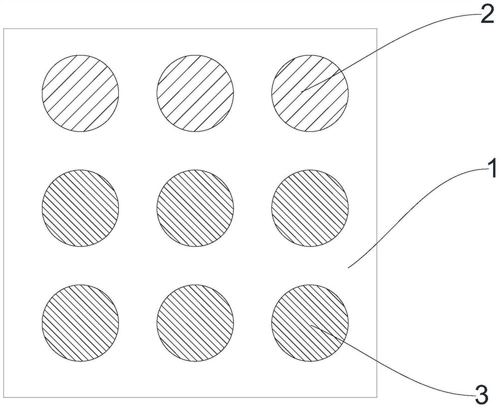
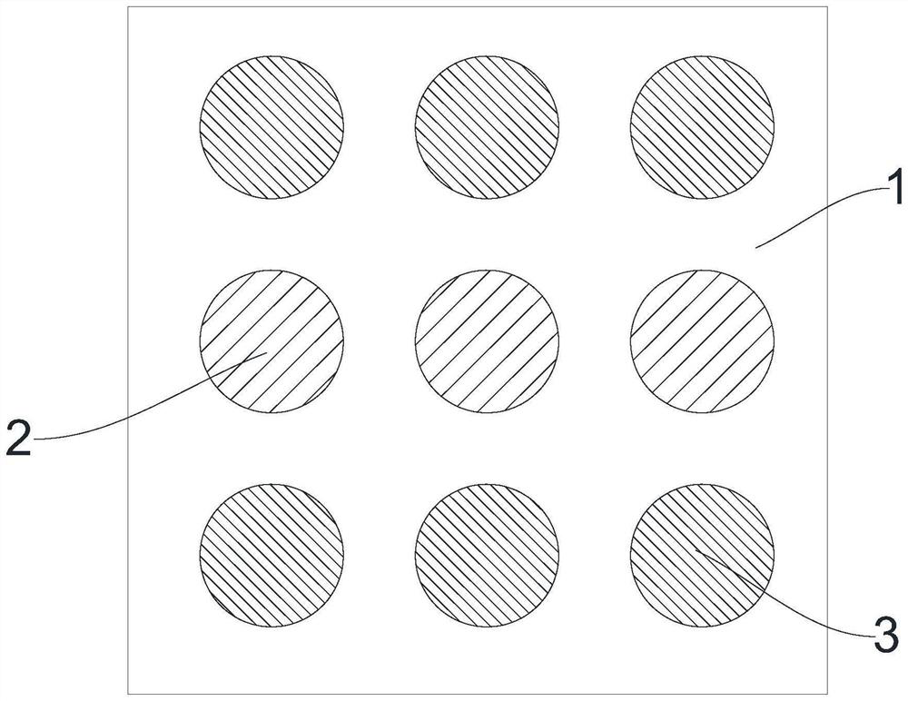
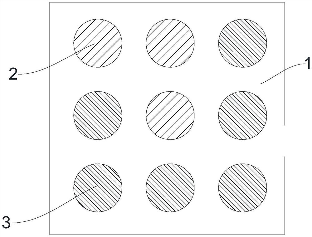
[0030] see Figure 1-6 , a method for arranging pin positions of a hybrid power connector, comprising the following steps:

[0031] 1) Arranging the three power lines 2 and the six signal lines 3 in the hybrid power connector 1 parallel to each other;

[0032] 2) Making the projections of the three power lines 2 and the six signal lines 3 on the cross section of the hybrid power connector 1 form a nine-square shape.

[0033] In this embodiment, when making, first arrange the three power lines 2 and the six signal lines 3 in the power connector 1 horizontally, and at this time, make the three power lines 2 and the six signal lines 3 mixed The projections on the cross-section of the power connection 1 are arranged in 3 rows and 3 columns, that is, in the shape of a nine palace. After this arrangement, the signal line 3 on the hybrid power connector 1 and the power line 2 do not interfere with each other. The cross-sectional area of ​​the entire hybrid power connector 1 is maxi...


PUM


Abstract

The invention belongs to the technical field of electric connector manufacturing, and particularly relates to a Pin position arrangement method of a hybrid power connector, which comprises the following steps of: 1) arranging three power lines and six signal lines in the hybrid power connector in parallel; (2) the projections of the three power lines and the six signal lines on the cross section of the hybrid power connector are made to be in a nine-grid shape, the mode that the three power lines are matched with the six signal lines is adopted, the Pin position arrangement method on the hybrid power connector is researched, the hybrid power connector manufactured through the method has the advantages that the structure is simple, and the cost is low. Therefore, the signal line and the power line on the hybrid power supply connector do not interfere with each other, transmission of signals and electric energy can be met, the utilization rate of the cross section of the hybrid power supply connector can be improved, and the hybrid power supply connector can meet transmission of signals and electric energy and can also meet the utilization rate of the cross section of the hybrid power supply connector. And the utilization rate of the cross section of the hybrid power supply connector can be improved.

Description

technical field [0001] The invention belongs to the technical field of manufacturing electric connectors, and specifically relates to a method for arranging pins of a hybrid power connector. Background technique [0002] There are power lines and signal lines in the hybrid power connector, so that both signal transmission and power transmission can be carried out, but since the current connectors are all single, either for power transmission or for signal transmission, therefore, There is no research on the number and arrangement of signal lines and power lines inside the hybrid power connector, but the power connector needs to adapt to the current common equipment, and the cross-section of the power connector should be improved during use. rate, so that after being plugged into the execution device, the surface area of ​​the execution device should be saved as much as possible, so that there is enough space on the execution device to connect other devices (reserved such as ...

Claims


Application Information

Patent Timeline
Patent Type & Authority Applications(China)
IPC IPC(8): H01R43/28
CPCH01R43/28
Inventor 余开刚郭斌何志刚陈进嵩
Owner GOLDENCONN ELECTRONICS TECH CO LTD
Why Eureka
Try Eureka