Cleaning device with water quality detection function and intelligent circulating self-cleaning method thereof

A technology for water quality testing and cleaning devices, applied in cleaning devices, cleaning equipment, cleaning machinery, etc., can solve problems such as poor user experience, increase in bacteria, and more labor burdens, so as to improve efficiency, improve cleaning effects, and avoid sewage. cross flow effect

Pending Publication Date: 2022-05-13
深圳市银舍创新科技有限公司
View PDF0 Cites 0 Cited by
  • Summary
  • Abstract
  • Description
  • Claims
  • Application Information

AI Technical Summary

Problems solved by technology

[0003] However, in daily use, as the number of times of use or the area to be cleaned increases and the cleaning environment is different, it is easy to make the cleaning head of the floor scrubber A lot of dirt accumulates, if it is not cleaned in time, it will cause unclean cleaning in the subsequent use, more stains remain on the cleaned ground, and bacteria increase, etc. At the same time

Method used


Image

  • Cleaning device with water quality detection function and intelligent circulating self-cleaning method thereof
  • Cleaning device with water quality detection function and intelligent circulating self-cleaning method thereof
  • Cleaning device with water quality detection function and intelligent circulating self-cleaning method thereof

Examples


Example Embodiment

[0035] Example 1

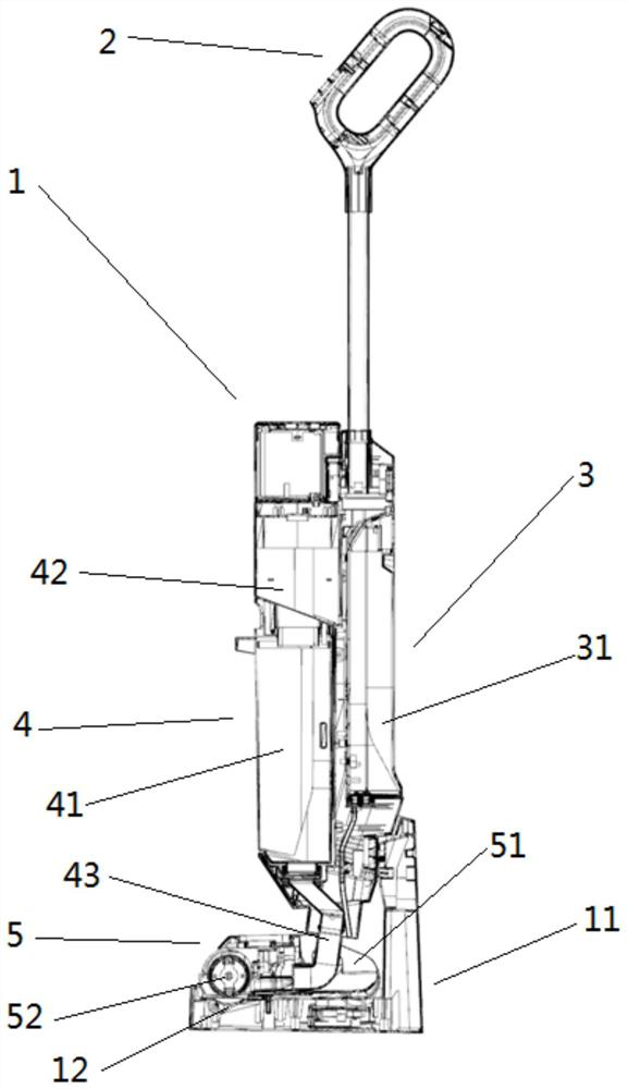
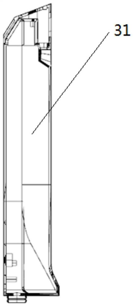
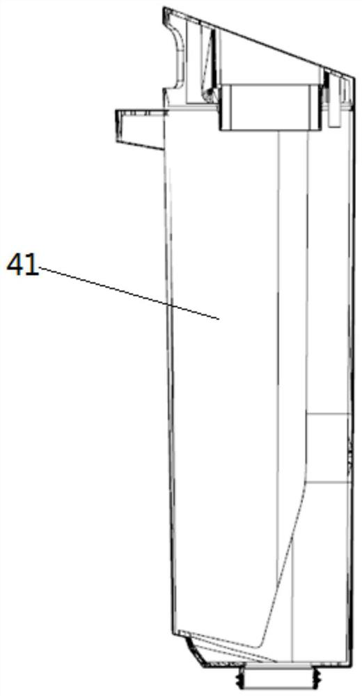
[0036] like Figure 1 to Figure 6The shown cleaning device with water quality detection includes a main body 1 and a tray support 11 . The main body 1 is provided with a control system 2 , a cleaning liquid supply system 3 , a sewage recovery system 4 and a cleaning system 5 . The control system 2 is electrically connected with the cleaning liquid supply system 3 , the sewage recovery system 4 and the cleaning system 5 . When the main body 1 is mounted on the tray holder 11 , the cleaning system 5 can be cleaned. In addition, the control system 2 is provided with a program preset module. The tray bracket 11 is provided with a TDS water quality detector 111 and a conductive contact 112 . The TDS water quality detector 111 is located at the bottom of the tray bracket 11 . The conductive contacts 112 are located on top of the tray holder 11 . In addition, the TDS water quality detector 111 is electrically connected to the conductive contact 112 . Meanwhi...

Example Embodiment

[0049] Example 2

[0050] like Figure 1 to Figure 6 The shown cleaning device with water quality detection includes a main body 1 and a tray support 11 . The main body 1 is provided with a control system 2 , a cleaning liquid supply system 3 , a sewage recovery system 4 and a cleaning system 5 . The control system 2 is electrically connected with the cleaning liquid supply system 3 , the sewage recovery system 4 and the cleaning system 5 . When the main body 1 is mounted on the tray holder 11 , the cleaning system 5 can be cleaned. In addition, the control system 2 is provided with a program preset module. The tray bracket 11 is provided with a TDS water quality detector 111 and a conductive contact 112 . The TDS water quality detector 111 is located at the bottom of the tray bracket 11 . The conductive contacts 112 are located on top of the tray holder 11 . In addition, the TDS water quality detector 111 is electrically connected to the conductive contact 112 . Meanwh...


PUM


Abstract

The invention provides a cleaning device with a water quality detection function. The cleaning device comprises a main machine body and a tray support. A control system, a cleaning liquid supply system, a sewage recovery system and a cleaning system are arranged on the main machine body. And the control system is electrically connected with the cleaning liquid supply system, the sewage recovery system and the cleaning system. When the main machine body is installed on the tray support, the cleaning system can be cleaned. And a program presetting module is arranged in the control system. And a TDS water quality detector and a conductive contact are arranged in the tray bracket. And the TDS water quality detector is positioned at the bottom of the tray bracket. The conductive contacts are located at the top of the tray support. And the TDS water quality detector is electrically connected with the conductive contact.

Description

technical field [0001] The invention belongs to the field of cleaning small household appliances, in particular to a cleaning device with water quality detection and an intelligent cycle self-cleaning method thereof. Background technique [0002] In daily life, due to the abundance of daily necessities, the cleaning device has been subdivided a lot, which brings a lot of convenience. When cleaning floors, tile floors and other ground environments, there is a cleaning device that can be specially used to clean floors, tile floors, etc., which integrates functions such as scrubbing, and is more convenient to use. At the same time, it can use water more efficiently. Saving, usually the full water capacity of a fresh water tank can clean a space of 200 square meters to 300 square meters. [0003] However, in daily use, as the number of times of use or the area to be cleaned increases and the cleaning environment is different, it is easy to accumulate more dirt on the cleaning h...

Claims


Application Information

Patent Timeline
IPC IPC(8): A47L11/30A47L11/40G01N33/18
CPCA47L11/302A47L11/4094A47L11/4083A47L11/4091G01N33/18A47L2201/00A47L2201/02A47L2201/028
Inventor 李建海赵巍
Owner 深圳市银舍创新科技有限公司
Why Eureka
Try Eureka