Efficient compression system for realizing air separation

A compression system and air separation technology, applied in separation methods, cold treatment separation, and dispersed particle separation, etc., can solve the problems of reduced compression efficiency, large air intake resistance, and blockage of filter elements, and achieve the effect of improving compression efficiency

Pending Publication Date: 2022-05-13
开封黄河空分集团有限公司
View PDF10 Cites 1 Cited by
  • Summary
  • Abstract
  • Description
  • Claims
  • Application Information

AI Technical Summary

Problems solved by technology

[0002] Air separation is a device that uses air as the raw material, turns the air into a liquid state through the deep freezing method of the compression cycle, and then gradually separates it from the liquid air through rectification to produce inert gases such as oxygen, nitrogen, and argon. Air separation is a necessary procedure, and the efficiency of air compression is directly related to the efficiency of air separation. The air compression of existing air separation equipment needs to compress the air mainly through the air compressor. In order to ensure the cleanliness of the air, the air compression system It includes an air filter device, which is used to filter dust and sundries in the air, but the filter element of the existing air filter device is blocked after a long time of use, resulting in a large intake resistance and a decrease in compression efficiency. To solve this problem, the existing In the technology, a cleaning device for the air filter element will be added, and the operation of the cleaning device will be controlled by detecting the intake air volume. When the filter element is blocked and the intake air volume is insufficient, the cleaning device will work to clean the filter element. Clean up in time when it is clogged, but it still needs to be shut down during the cleaning process, and when the filter element is partially damaged, the air intake can meet the requirements, but a lot of dust will enter, and the dust will adhere to the compressor blades, resulting in a loss of compressor compression efficiency. reduce

Method used


Image

  • Efficient compression system for realizing air separation
  • Efficient compression system for realizing air separation
  • Efficient compression system for realizing air separation

Examples


Embodiment 1

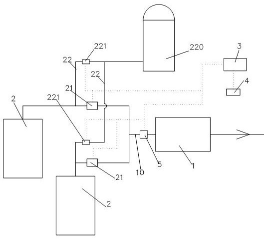
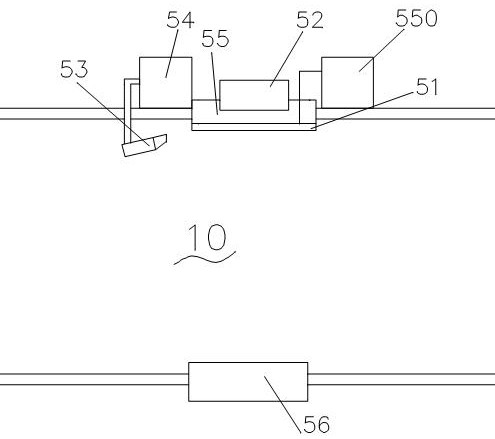
[0033] The invention provides a high-efficiency compression system for realizing air separation, referring to figure 1 , figure 2 , as a specific embodiment, the system includes a gas compressor 1, an air inlet 10 arranged at the air inlet of the gas compressor 1, at least two air filter devices 2 connected to the air inlet 10, A control valve 21 is provided between each of the air filter devices 2 and the air inlet, and also includes a control device 3, a humidity detection device 4 for detecting ambient humidity, and a micrometer arranged on the air inlet 10. Dust detection device 5 , the control device 3 is used to acquire the detection values ​​of the humidity detection device 4 and the dust detection device 5 to control the opening and closing of the control valve 21 .

[0034]Specifically, for the convenience of description, two air filter devices 2 are provided here as an example. In this arrangement, when the compression system compresses the air, the control device ...

Embodiment 2

[0043] The present invention provides a high-efficiency compression system for realizing air separation, which is different from Embodiment 1 in that the air filtering device 2 is provided with a cleaning device, and the cleaning device includes a back-blowing branch 22, and the back-blowing One end of the branch is connected between the air filter device 2 and the corresponding control valve 21 , the other end is in communication with the high-pressure air source 220 , and each of the blowback branches 22 is provided with a solenoid valve 221 . refer to figure 1 , image 3 , by setting the back blowing branch to communicate with the high-pressure air source 220, when the air filter device 2 is used, the control device 4 controls the corresponding solenoid valve 221 to open, and the high-pressure air source enters along the air pipe 201 of the air filter device 2 for back blowing, Thereby, the fine dust attached to the filter element of the air filter device 2 is removed to a...

Embodiment 3

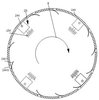
[0056] The present invention provides a high-efficiency compression system for realizing air separation, which is different from Embodiment 2 in that a plurality of connecting rods 245 are evenly spaced around the outer casing 241 on the outer side of the outer casing, and the cover body 242 is provided with a plurality of connecting parts 246 corresponding to the connecting rods one by one, and the connecting parts 246 are quickly detachably connected with the connecting rods 245 . Through the quick release connection, the cylindrical filter element can be replaced conveniently and quickly, avoiding the downtime of the compression system caused by the long time for replacing the filter element, and further ensuring the working efficiency of the compression system.

[0057] Further, refer to image 3 , Image 6 , Figure 7 , as a specific embodiment, the connection between the outer shell and the cover is as follows: the connecting part 246 includes a columnar member 2460 ro...


PUM


Abstract

The invention provides an efficient compression system for realizing air separation, which comprises a gas compressor, an air inlet channel arranged at an air inlet of the gas compressor, and at least two air filtering devices communicated with the air inlet channel, and a control valve is arranged between each air filtering device and the air inlet. The air purifier further comprises a control device, a humidity detection device used for detecting environment humidity and a tiny dust detection device arranged on the air inlet channel, the control device is used for obtaining detection values of the humidity detection device and the tiny dust detection device so as to control opening and closing of the control valve, and replacement of the air filtering device can be directly controlled according to the content of tiny dust in the air inlet channel. According to the air compressor, dust is prevented from being excessively attached to blades of the air compressor, the influence that the compression efficiency is reduced due to the fact that the dust is attached to the blades can be reduced, the compression efficiency of the compression system is improved, the air filtering device does not need to be cleaned and shut down at the same time through the method of directly switching the air filtering device, and the compression efficiency is further improved.

Description

technical field [0001] The invention generally relates to the technical field of air separation, in particular to an efficient compression system for realizing air separation. Background technique [0002] Air separation is a device that uses air as the raw material, turns the air into a liquid state through the deep freezing method of the compression cycle, and then gradually separates it from the liquid air through rectification to produce inert gases such as oxygen, nitrogen, and argon. Air separation is a necessary procedure, and the efficiency of air compression is directly related to the efficiency of air separation. The air compression of existing air separation equipment needs to compress the air mainly through the air compressor. In order to ensure the cleanliness of the air, the air compression system It includes an air filter device, which is used to filter dust and sundries in the air, but the filter element of the existing air filter device is blocked after a lo...

Claims


Application Information

Patent Timeline
Patent Type & Authority Applications(China)
IPC IPC(8): B01D46/42B01D46/71B01D46/72B01D46/88F25J3/04
CPCB01D46/4227F25J3/04163F25J2205/84F25J2205/86
Inventor 彭辉
Owner 开封黄河空分集团有限公司
Why Eureka
Try Eureka