
Chemical waste gas cooling, liquefying and absorbing device

An absorption device and exhaust gas technology, applied in chemical instruments and methods, separation methods, lighting and heating equipment, etc., can solve the problems of inability to exchange coolant, reduce waste gas treatment efficiency, and low efficiency of coolant use, and achieve liquefaction effects Good, easy to handle, and avoid environmental pollution

Inactive Publication Date: 2022-05-13
东营国滋电子科技有限公司
View PDF4 Cites 0 Cited by
  • Summary
  • Abstract
  • Description
  • Claims
  • Application Information

AI Technical Summary

Problems solved by technology

[0004] The purpose of the present invention is to solve the problem that when the existing chemical exhaust gas cooling and liquefaction absorption device liquefies the exhaust gas, after the exhaust pipe and the cooling liquid perform heat exchange, the cooling liquid around the exhaust pipe will heat up due to the cooling liquid being in a stagnant state. After that, it cannot exchange with the surrounding cooling liquid in time, which leads to the low efficiency of the cooling liquid and greatly reduces the treatment efficiency of the waste gas. A kind of chemical waste gas cooling and liquefaction absorption device is proposed

Method used


Image

  • Chemical waste gas cooling, liquefying and absorbing device
  • Chemical waste gas cooling, liquefying and absorbing device
  • Chemical waste gas cooling, liquefying and absorbing device

Examples


Embodiment 1

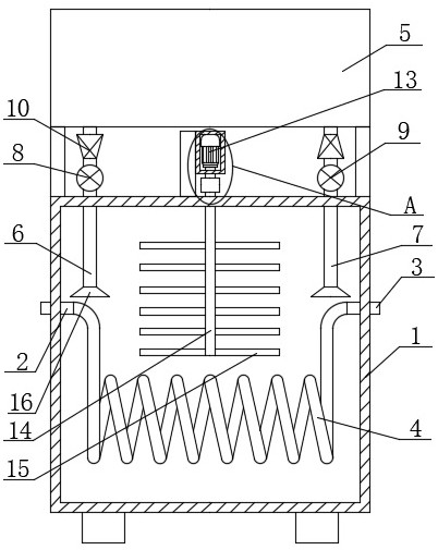
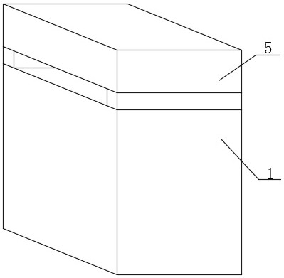
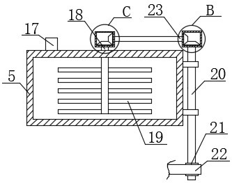
[0027] refer to Figure 1-6 , a chemical waste gas cooling and liquefaction absorption device, comprising a box body 1, an inlet pipe 2 is fixedly installed on one side of the box body 1, and an outlet pipe 3 is fixedly installed on the other side of the box body 1, the inlet pipe 2 and the outlet pipe 3 is fixedly installed with a liquefaction pipe 4, the top of the box body 1 is fixedly installed with a heat exchange box 5, the bottom of the heat exchange box 5 is fixedly installed with an outlet pipe 6, and the bottom of the heat exchange box 5 is fixedly installed with a water inlet pipe 7 and an outlet pipe A main pump 8 is fixedly installed on the 6, an auxiliary pump 9 is fixedly installed on the water inlet pipe 7, a check valve 10 is fixedly installed on the water inlet pipe 7 and the water outlet pipe 6, and both the water inlet pipe 7 and the water outlet pipe 6 are fixedly installed There is a connection cover 16, a drive motor 13 is fixedly installed on the top of...

Embodiment 2

[0037] refer to Figure 1-6, a chemical waste gas cooling and liquefaction absorption device, comprising a box body 1, an inlet pipe 2 is fixedly installed on one side of the box body 1, and an outlet pipe 3 is fixedly installed on the other side of the box body 1, the inlet pipe 2 and the outlet pipe 3 is fixedly installed with a liquefaction pipe 4, the top of the box body 1 is fixedly installed with a heat exchange box 5, the bottom of the heat exchange box 5 is fixedly installed with an outlet pipe 6, and the bottom of the heat exchange box 5 is fixedly installed with a water inlet pipe 7 and an outlet pipe A main pump 8 is fixedly installed on the 6, an auxiliary pump 9 is fixedly installed on the water inlet pipe 7, a check valve 10 is fixedly installed on the water inlet pipe 7 and the water outlet pipe 6, and both the water inlet pipe 7 and the water outlet pipe 6 are fixedly installed There is a connection cover 16, a drive motor 13 is fixedly installed on the top of ...


PUM


Abstract

The invention belongs to the technical field of chemical waste gas treatment, particularly relates to a chemical waste gas cooling, liquefying and absorbing device, and aims to solve the problem that when an existing chemical waste gas cooling, liquefying and absorbing device liquefies waste gas, after an exhaust pipe exchanges heat with cooling liquid, the cooling liquid is in a non-flowing state; in order to solve the problems of low use efficiency of the cooling liquid and great reduction of waste gas treatment efficiency due to the fact that the cooling liquid around an exhaust pipe cannot be exchanged with the surrounding cooling liquid in time after being heated, the invention provides the following scheme: the waste gas treatment device comprises a box body, a gas inlet pipe is fixedly mounted on one side of the box body, and a discharge pipe is fixedly mounted on the other side of the box body; liquefying pipes are fixedly installed on the air inlet pipe and the discharging pipe, and a heat exchange box is fixedly installed on the top of the box body. According to the device, waste gas can be liquefied and retreated, environmental pollution is avoided, the liquefaction effect of the device on the waste gas is good, and the waste gas treatment efficiency is greatly improved.

Description

technical field [0001] The invention relates to the technical field of chemical waste gas treatment, in particular to a cooling and liquefaction absorption device for chemical waste gas. Background technique [0002] In the process of chemical production, as the chemical reaction proceeds, a large amount of solvents or reactants with lower boiling points will volatilize to form waste gas. The waste gas is directly discharged into the atmosphere and will easily cause environmental pollution. Therefore, it is usually necessary to liquefy the waste gas first. . [0003] However, when the existing chemical exhaust gas cooling and liquefaction absorption device liquefies the exhaust gas, after the exhaust pipe and the cooling liquid perform heat exchange, because the cooling liquid is in a stagnant state, the cooling liquid around the exhaust pipe cannot be in time with the surrounding after heating up. The coolant is exchanged, which in turn leads to low efficiency of coolant u...

Claims


Application Information

Patent Timeline
Patent Type & Authority Applications(China)
IPC IPC(8): B01D53/00B01D53/18F28D21/00F28F13/12
CPCB01D53/002B01D53/18F28D21/0003F28F13/125
Inventor 韩宗
Owner 东营国滋电子科技有限公司
Learn More