Steam distillation device for effectively separating oil-water mixture
A technology for steam distillation and separation of oil and water, applied in separation methods, liquid separation, essential oils/spices, etc., can solve the problems of poor reflux effect, narrow application range, slow reflux rate, etc., and achieve good oil-water separation effect and applicable The effect of wide range and high reflow efficiency
- Summary
- Abstract
- Description
- Claims
- Application Information
AI Technical Summary
Problems solved by technology
Method used
Image

Examples
Embodiment 1
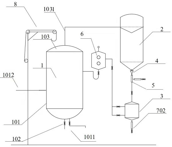
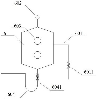
[0027] A steam distillation device for effectively separating oil-water mixture, such as figure 1 Shown, comprise reactor 1, condenser 2, oil-water separator 3 and reflux tank 6, wherein reactor 1 top is provided with kettle cover 103, reactor 1 is provided with jacket 101, and jacket 101 is provided with steam outlet pipe 1011 and The steam inlet pipe 1012 is provided with a safety valve and a pressure gauge, and the bottom of the reaction kettle 1 is provided with a liquid outlet, and the liquid outlet is provided with a liquid outlet valve 102 . A breathing cap 602 is installed on the top of the return tank 6 . The connection relationship of several main components is as follows:
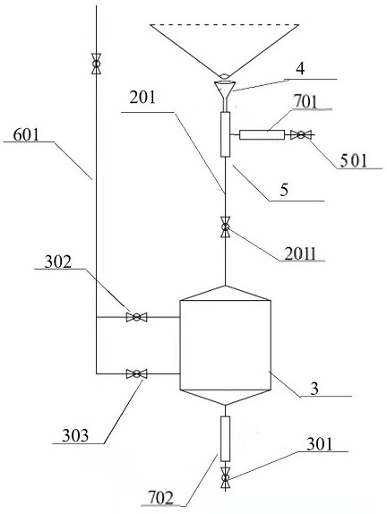
[0028] The top of the reaction kettle 1 is provided with a gas phase pipeline 1031 and connected to the condenser 2, the liquid outlet at the bottom of the condenser 2 is connected to the top of the oil-water separator 3 through the funnel 4 and the condensate pipeline 201, and the oil-water sep...
Embodiment 2
[0032] Further optimization can be carried out on the basis of Embodiment 1, such as figure 2 , 3 As shown, a visible glass tube 5 is provided on the condensate pipeline 201, and the side of the visible glass tube 5 is connected to the first outlet valve 501 through a pipeline, and the visible glass tube 5 and the pipeline of the first outlet valve 501 are provided with The first viewing mirror 701 is convenient for observation and sampling of condensate. A control valve 2011 is provided on the condensate pipeline 201 between the sight glass tube 5 and the oil-water separator 3 .
[0033] The bottom of the oil-water separator 3 is connected to the second outlet valve 301 through a pipeline, and a second sight glass 702 is arranged on the pipeline between the oil-water separator 3 and the second outlet valve 301 to facilitate observation of the separation state of the oil-water mixture.
[0034] One side of the reflux tank 6 is connected to the reflux pipeline 601 through a ...
Embodiment 3
[0036] On the basis of Embodiment 1 and Embodiment 2, the present invention is equipped with a manual crane 8 on one side of the reactor 1 for hoisting the internal hopper of the reactor 1 . A pressure gauge and a safety valve are arranged on the top of the kettle cover 103 to ensure safe use.
[0037] The concrete use process of the present invention is as follows:
[0038] Before work, close the reactor liquid outlet valve 102, turn the manual crane 8 to open the reactor lid 103, add water once, cover the kettle lid 103 and tighten the fasteners, open the steam inlet valve and the outlet valve, and heat up the water once. When the condensate pipeline 201 at the lower end of the condenser has condensate flowing out, observe the clarity of the liquid through the sight glass tube 5 and the first sight glass 701 until the system is cleaned and qualified, stop heating, close the steam valve, and open the liquid valve 102 , discharge waste water.
[0039]When working, close the ...
PUM
 Abstract
Description
Claims
Application Information