Protective equipment for wind power generation

A protective equipment, integrated technology, applied in the direction of wind energy power generation, wind turbines, mechanical equipment, etc., can solve the problem of generator heat is not easy to dissipate, affect the service life, reduce the use performance and other problems, to improve work efficiency and performance, not easy to block , the effect of improving performance

Pending Publication Date: 2022-05-13
王文平
View PDF0 Cites 0 Cited by
  • Summary
  • Abstract
  • Description
  • Claims
  • Application Information

AI Technical Summary

Problems solved by technology

[0005] Aiming at the deficiencies of the prior art, the present invention provides a protective device for wind power generation, which solves the problem that most wind power generators are exposed outside, especially in some dry areas of our country, a large amount of dust accumulates on the surface of the generator, making Generator heat is not easy to dissipate, it is prone to high temperature, low working efficiency, and affects the service life at the same time, reducing the performance

Method used


Image

  • Protective equipment for wind power generation
  • Protective equipment for wind power generation
  • Protective equipment for wind power generation

Examples


Embodiment example 1

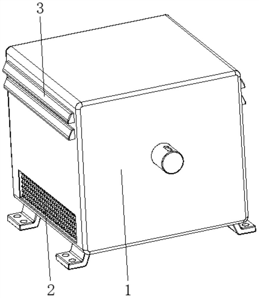
[0032] see Figure 1-7 , the present invention provides a technical solution: a protective device for wind power generation, including a box 1, a partition 2, and a cover 3, the partition 2 is fixed on the two sides corresponding to the bottom of the surface of the box 1, and the cover 3 is fixed On both sides corresponding to the top part of the surface of the box body 1, the cover plate 3 corresponds to the position of the partition net 2;

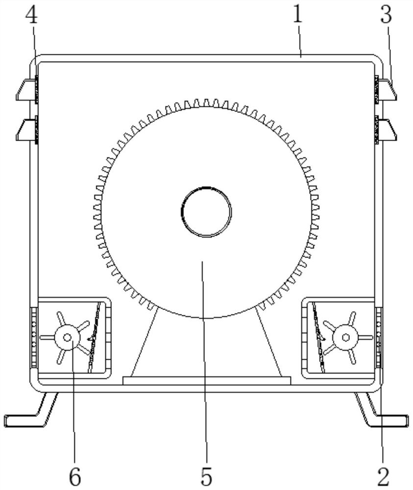
[0033] The interior of the box body 1 is provided with a dustproof filter screen 4, a wind power generator 5, and an integrated processing device 6. The dustproof filter screen 4 is fixed on the inner wall of the box body 1 and is located at the position of the cover plate 3, and the wind power generator 5 is fixed on the box body. The bottom of the inner wall of the body 1 is located in the center, and the integrated processing device 6 is arranged inside the box body 1 and located at the position of the partition net 2, which can dissi...

Embodiment example 2

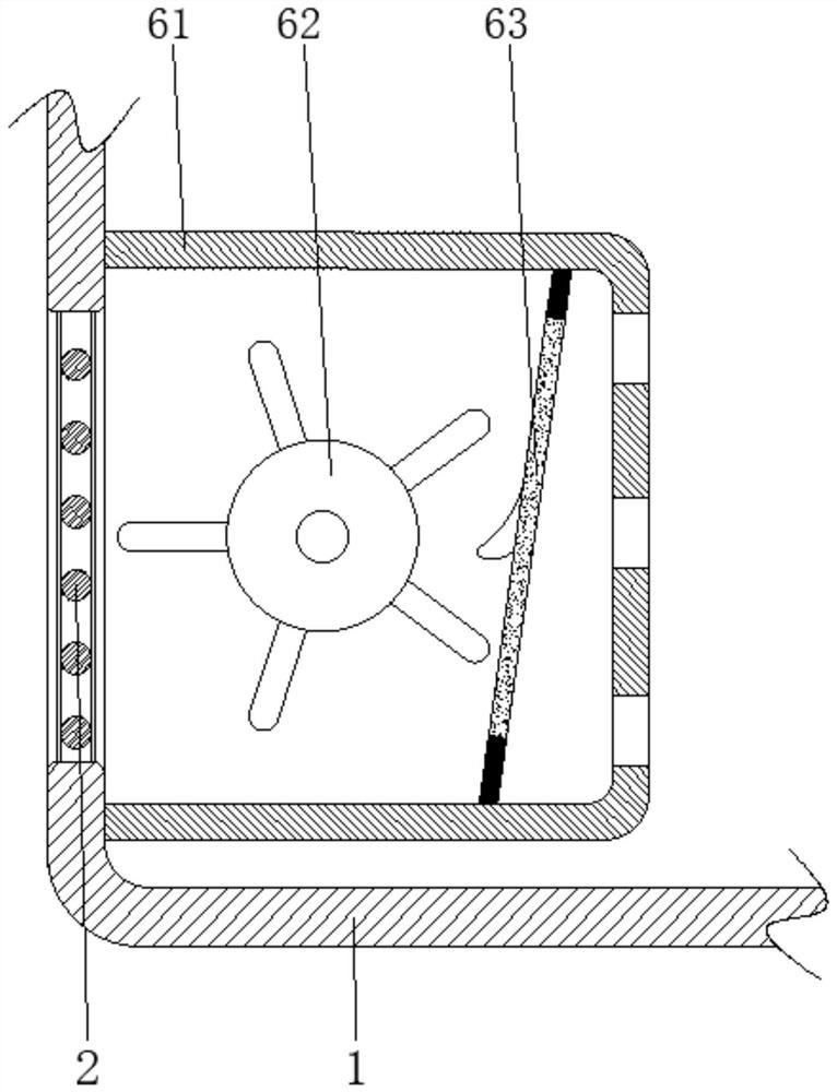
[0035] The integrated processing device 6 is provided with a U-shaped housing 61, a heat dissipation device 62, and a dust removal device 63. The open end of the U-shaped housing 61 faces the partition net 2 and is fixedly connected with the inner wall of the box body 1. The heat dissipation device 62 is arranged on the U-shaped housing. The inside of the body 61 is close to the central position, and the dust removal device 63 is arranged on the inner side of the U-shaped housing 61. The cooling device 62 is connected with the dust removal device 63, which makes full use of its own rotation during heat dissipation and reduces the impact on power. Use, combined with the mutual cooperation between the heat dissipation device 62 and the dust removal device 63, has played the effect of heat dissipation and dust removal at the same time, and achieved multiple functions.

Embodiment example 3

[0037]The cooling device 62 is provided with a drive roller 621, a fan blade device 622, and a ball 623. The end of the drive roller 621 is rotatably connected to the inner wall of the U-shaped housing 61. The fan blade device 622 is arranged inside the drive roller 621 and is located on the surface. The ball 623 is set on the surface of the fan blade device 622 and away from the end of the driving roller 621. When the driving roller 621 drives the fan blade device 622 to rotate, it can drive the air in the box 1 in time and discharge it from the dustproof filter 4 , and the external space enters the box body 1, so that the air circulation is used to quickly dissipate heat from the wind turbine 5, and at the same time, the rotating fan blade device 622 uses the ball 623 to roll on the arc surface gradual protrusion 633 to reduce friction , and press the frame 631 and shake it to make the whole rotation process smoother, and use the action force and reaction force to make the el...


PUM


Abstract

The protection equipment comprises a box body, separation nets and cover plates, the separation nets are fixed to the two corresponding sides of the bottom of the surface of the box body, the cover plates are fixed to the two corresponding sides of the top of the surface of the box body, and the positions of the cover plates correspond to the positions of the separation nets. A dustproof filter screen, a wind driven generator and an integrated treatment device are arranged in the box body, the dustproof filter screen is fixed to the inner wall of the box body and located at the position of the cover plate, the wind driven generator is fixed to the bottom of the inner wall of the box body and located in the center, and the integrated treatment device is arranged in the box body and located at the position of the partition net; the invention relates to the technical field of wind power generation equipment. According to the protection equipment for wind power generation, the purposes of dust prevention and heat dissipation are achieved, heat can be dissipated in time, dust entering is reduced, dust accumulation is effectively prevented, meanwhile, the self-cleaning effect is achieved, the blocking situation is not prone to occurring, and the working efficiency and the use performance are improved.

Description

technical field [0001] The invention relates to the technical field of wind power generation equipment, in particular to protective equipment for wind power generation. Background technique [0002] As a clean and renewable energy, wind energy has been paid more and more attention by countries all over the world. Wind power refers to converting the kinetic energy of wind into electrical energy. Wind is a non-polluting energy source. Using wind power to generate electricity is very environmentally friendly and can generate huge amounts of electricity. Therefore, more and more countries pay more attention to wind power generation. The generator is an essential component in wind power generation. A wind turbine is a power device that converts wind energy into mechanical work, which drives the rotor to rotate, and finally outputs alternating current. A wind turbine generally has a wind wheel, a generator including a device, a steering fin, a tower, a speed limit safety mechani...

Claims


Application Information

Patent Timeline
Patent Type & Authority Applications(China)
IPC IPC(8): F03D80/55F03D80/00F03D80/60B08B7/02
CPCF03D80/55F03D80/00F03D80/60B08B7/02Y02E10/72
Inventor 王文平
Owner 王文平
Why Eureka
Try Eureka