Civil aviation navigation equipment sight distance coverage analysis method combined with flight path variable height

A technology of flight trajectory and navigation equipment, applied in the field of line-of-sight coverage analysis of civil aviation navigation equipment combined with flight trajectory variable height, can solve problems such as inability to guarantee flight safety, and achieve the effect of ensuring flight safety, ingenious conception, and scientific design

Active Publication Date: 2022-05-13
THE SECOND RES INST OF CIVIL AVIATION ADMINISTRATION OF CHINA
View PDF20 Cites 0 Cited by
  • Summary
  • Abstract
  • Description
  • Claims
  • Application Information

AI Technical Summary

Problems solved by technology

[0005] The purpose of the present invention is to provide a method for analyzing the line-of-sight coverage of civil aviation navigation equipment in combination with the variable altitude of the flight track, so as to solve the problem that there is no method for analyzing the line-of-sight coverage of the flight track with variable altitude in the prior art, and the problem of flight safety cannot be guaranteed.

Method used


Image

  • Civil aviation navigation equipment sight distance coverage analysis method combined with flight path variable height
  • Civil aviation navigation equipment sight distance coverage analysis method combined with flight path variable height
  • Civil aviation navigation equipment sight distance coverage analysis method combined with flight path variable height

Examples


Embodiment 1

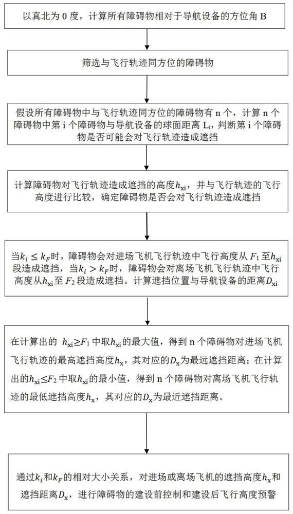
[0133] as attached Figure 5 As shown, the present invention provides an example of an airport applying the method of the present invention to carry out line-of-sight coverage analysis, specifically comprising the following steps:

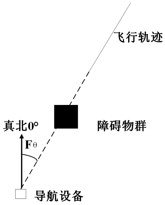
[0134] S1. Taking true north as 0 degrees, calculate the azimuth angle B of all obstacles relative to the navigation equipment, unit °;

[0135] In the S1, the calculation formula of the azimuth B is:

[0136] B=90-A+360×T (1)

[0137] T=A / 360, rounded down (2)

[0138] A=atan2(x,y) , converted into angle (3)

[0139] x = sin( O j - N j ) ×cos( O w ) (4)

[0140] y = cos( N w )×sin( O w )- sin( N w ) ×cos( O w ) ×cos( O j - N j ) (5)

[0141] in,( O w , O j ): the coordinates of the obstacle, where, O w is the latitude, O j is the longitude;

[0142] ( N w , N j ) coordinates of the navigation device, where, N w is the latitude, N j is the longitude.

[0143] S2. Screen the obstacles with the same orientatio...

example 1

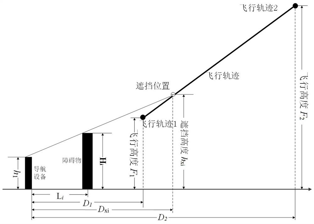
[0192] Example 1: Fθ=20°, h 1 = 100 meters, H i =250 meters, F 1 =300 meters, D 1 =2500m, F 2 =900 meters, D 2 =6000m.

[0193] 1. Since the obstacle has a width, the azimuth range between the obstacle and true north is calculated according to the boundary of the obstacle. After calculation, the azimuth angles formed by the left and right boundaries of the obstacle and the true north are 11.90° and 21.5° respectively, so the azimuth angle range of the obstacle is 11.9°~21.5°.

[0194]2. Fθ is located within the range of obstacle azimuth 11.9°~21.5°, therefore, the obstacle is in the same orientation as the flight path.

[0195] 3. After calculation, the shortest distance L between the left and right boundaries of the obstacle and the navigation equipment i =1508m.

[0196] Satisfy 0i D 2 , so it may cause obstruction to the flight path.

[0197] 4. After calculation, k i =0.1, k F =0.17, k i k F , h xi = 416 meters, therefore, h xi > F 1 , obstacles...

example 2

[0200] Example 2: Fθ=20°, h 1 = 100 meters, H i = 400 meters, F 1 =600 meters, D 1 =2000m, F 2 =900 meters, D 2 =6000m.

[0201] Since the azimuth angle formed by the connection line between the flight track and the navigation equipment and the true north is Fθ, the obstacle coordinates ( O w , O j ) and navaid coordinates ( N w , N j ) has not changed, therefore, the calculation process of judging whether an obstacle may block the flight path in the first three steps is the same as that of Example 1, so it will not be repeated, and the calculation will start from step 4 below.

[0202] 4. After calculation, k i =0.20, k F =0.075, k i > k F , h xi = 661 meters, therefore, h xi F 2 , obstacles will block the flight path from 661 meters to 900 meters, marked as a dotted line, and 600 meters to 661 meters will not cause obstruction, marked as a solid line.

[0203] 5. After calculation, the distance between the occlusion position and the navigation ...


PUM


Abstract

The invention discloses a civil aviation navigation equipment sight distance coverage analysis method combined with variable height of a flight path, belongs to the technical field of civil aviation navigation equipment, and solves the problem that the flight safety cannot be ensured due to the absence of a method for carrying out sight distance coverage analysis on a variable height flight path in the prior art. The method comprises the following steps: S1, calculating azimuth angles B of all obstacles relative to navigation equipment by taking true north as 0 degree; s2, screening obstacles in the same direction as the flight path; and S3, calculating whether the n obstacles shield the flight path or not, and calculating the shielding position. The invention provides a method for calculating the shielding of the obstacle to the variable-height flight path for the first time, which comprises the specific shielding position, namely the critical position of the received signal from existence to absence, and the signal coverage condition on the flight path after shielding, so that a reference basis is provided for the height control of the obstacle and the adjustment of the flight height of the aircraft; and the flight safety is powerfully ensured.

Description

technical field [0001] The invention belongs to the technical field of civil aviation navigation equipment, and in particular relates to a sight range coverage analysis method for civil aviation navigation equipment combined with flight track variable altitude. Background technique [0002] Civil aviation ground-based navigation equipment mainly provides guidance for aircraft flight, such as omnidirectional beacons, which provide guidance for aircraft on the route and when they fly in and out of the field, while the instrument landing system provides localizer and glideslope guidance for aircraft approach, so that The aircraft aligns with the runway and descends at a defined glide angle until landing. Since the ground-based navigation equipment is a radio equipment, the electromagnetic wave signal emitted by the equipment and the signal received by the aircraft airborne equipment are easily affected by terrain and buildings. If encountering high obstacles, such as mountains ...

Claims


Application Information

Patent Timeline
Patent Type & Authority Applications(China)
IPC IPC(8): G01C21/20G01C5/00G01C3/00G01C1/00G08G5/00
CPCG01C21/20G01C3/00G01C5/005G01C1/00G08G5/0073
Inventor 林欢梁飞叶家全李沅锴许健袁斌杨萍孙彦龙李鑫李润文施瑞邹杰李清栋高静杨正波崔铠韬
Owner THE SECOND RES INST OF CIVIL AVIATION ADMINISTRATION OF CHINA
Why Eureka
Try Eureka