Supercharge Your Innovation With Domain-Expert AI Agents!

Beam combiner testing device and method

A test device and test method technology, which is applied in the field of laser detection, can solve problems such as output errors of optical beam combiners, and achieve the effects of reducing device loss, accurate results, and fast detection speed

Pending Publication Date: 2022-05-13
武汉思创精密激光科技有限公司
View PDF0 Cites 0 Cited by
  • Summary
  • Abstract
  • Description
  • Claims
  • Application Information

AI Technical Summary

Problems solved by technology

[0005] The purpose of the present invention is to provide a beam combiner testing device and method for the problem that the existing optical beam combiner is prone to output errors

Method used


Image

  • Beam combiner testing device and method
  • Beam combiner testing device and method
  • Beam combiner testing device and method

Examples


Embodiment 1

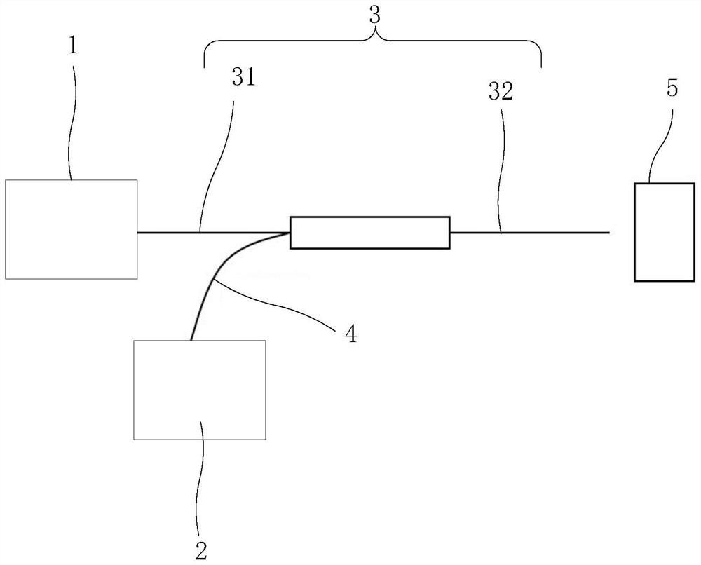
[0039] A kind of beam combiner testing device provided by the present invention is introduced below in conjunction with accompanying drawing;

[0040] see figure 1 , is a beam combiner testing device provided by the present invention, which includes: a first light source 1, a second light source 2, a signal fiber 3, a pump fiber 4 and a power meter 5, and the signal fiber 3 is provided with a sleeve to be The installation position of the test beam combiner, the beam combiner to be tested forms the signal fiber 3 into a signal fiber input fiber 31 and a signal fiber output fiber 32, and the signal fiber input fiber 31 is connected to the output end of the first light source 1 , the output end of the signal fiber output fiber 32 is aligned with the receiving end of the power meter 5, one end of the pump fiber 4 is connected to the output end of the second light source 2, and the other end of the pump fiber 4 forms a Connector to the beam combiner to be tested.

[0041] Specifi...


PUM


Abstract

The invention relates to a beam combiner testing device which comprises a first light source, a second light source, a signal fiber, a pumping fiber and a power meter, the signal fiber is provided with an installation position for sleeving a beam combiner to be tested, the beam combiner to be tested enables the signal fiber to form a signal fiber input fiber and a signal fiber output fiber, the signal fiber input fiber is connected with the output end of the first light source, and the pumping fiber is connected with the power meter. The output end of the signal fiber output fiber is aligned with the receiving end of the power meter, one end of the pumping fiber is connected with the output end of the second light source, and the other end of the pumping fiber forms a connecting end connected with the beam combiner to be tested. The invention further provides a beam combiner testing method. According to the beam combiner testing device and method, the first light source and the second light source which are connected with the number fiber input fiber and the pumping fiber respectively are arranged and used for detecting whether the beam combiner has problems or not; the detection speed is fast and the result is accurate. The device can help a worker to rapidly discriminate the beam combiner, and reduces the unnecessary loss of devices.

Description

technical field [0001] The invention relates to the technical field of laser detection, in particular to a beam combiner testing device and method. Background technique [0002] The beam combiner is an optical fiber device prepared on the basis of fused tapered optical fiber bundles. It arranges a bundle of optical fibers together in a certain way, heats them at high temperature to melt them, and at the same time stretches the optical fiber bundles in the opposite direction, and the heated area of ​​the optical fibers melts into a tapered optical fiber bundle. [0003] The main function of the beam combiner is to realize pump light coupling. Due to its advantages of high coupling efficiency, high integration, and convenient operation, the fiber combiner is indispensable in all-fiber high-power fiber lasers. In use, the beam combiner will have the following problems: 1. The signal light passes from the signal input fiber core of the beam combiner to the signal output fiber c...

Claims


Application Information

Patent Timeline
IPC IPC(8): G01M11/00
CPCG01M11/33
Inventor 李琦徐港陈翔杨宇李威
Owner 武汉思创精密激光科技有限公司
Features
  • R&D
  • Intellectual Property
  • Life Sciences
  • Materials
  • Tech Scout
  • Unparalleled Data Quality
  • Higher Quality Content
  • 60% Fewer Hallucinations
Learn More