
Circuit, method and chip for detecting signal

A technology for detecting signals and signals to be measured, which is applied in the directions of measuring electricity, measuring electrical variables, and electronic circuit testing, etc., which can solve problems such as false alarms, poor detection effect of analog sensors, and reduced sensor accuracy, and achieve low circuit cost and effective external environment. Environmental changes, stable and effective signal acquisition effect

Active Publication Date: 2022-06-21
BEIJING SMARTCHIP MICROELECTRONICS TECH COMPANY +1
View PDF4 Cites 0 Cited by
  • Summary
  • Abstract
  • Description
  • Claims
  • Application Information

AI Technical Summary

Problems solved by technology

[0003] The sensors integrated in mainstream security chips are various analog sensors such as temperature sensors, voltage sensors, clock frequency sensors and laser sensors, etc. However, the separation of sensor detection cannot adapt to various complex working environments, and local false alarms or The situation of local leakage alarm makes the detection effect of analog sensor poor
In addition, the portability of the analog sensor process is poor, and the process node of the integrated circuit is continuously upgraded. When developing a security chip based on a new circuit process, it is necessary to redesign and adjust the analog sensor circuit, which increases the cost and risk of research and development.
In addition, the scale of analog sensors is large, and some sensors are easy to be identified in the layout, and clever attackers will avoid sensors to perform fault injection attacks
Finally, the analog sensor is greatly affected by the environment, and the accuracy of the sensor will decrease when the environment changes

Method used


Image

  • Circuit, method and chip for detecting signal
  • Circuit, method and chip for detecting signal
  • Circuit, method and chip for detecting signal

Examples


Embodiment Construction

[0032] The specific implementations of the embodiments of the present invention will be described in detail below with reference to the accompanying drawings. It should be understood that the specific implementation manners described herein are only used to illustrate and explain the embodiments of the present invention, and are not used to limit the embodiments of the present invention.

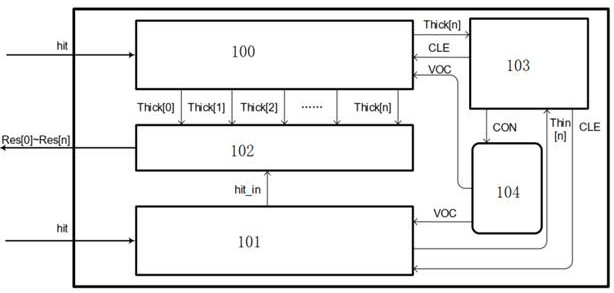
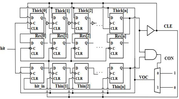
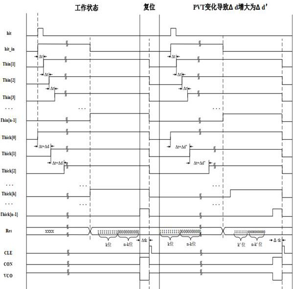
[0033] figure 1 is a schematic diagram of a circuit for detecting a signal according to the present invention, such as figure 1 As shown, the present invention provides a circuit for detecting a signal, the circuit at least includes: a delay unit and an output unit 102; the delay unit includes a first link 100 and a second link 101, the first The delay time of the link 100 is greater than the delay time of the second link 101. Preferably, the delay time range of the first link 100 is Δt+Δd~N (Δt+Δd); the second link 101 The delay time is NΔt, and the delay time of the first link 100 and th...


PUM


Abstract

Embodiments of the present invention provide a circuit, method and chip for detecting signals, the circuit at least includes: a delay unit and an output unit; the delay unit includes a first link and a second link, and the first link The delay of the path is greater than the delay of the second link, the first link is used to output the status signal when the signal to be tested passes, and the second link is used to output the sampling pulse when the signal to be tested passes ; The output unit is used to sample the state signal through the sampling pulse to obtain a sampling signal. The cost of the circuit for detecting the signal is low, no clock is needed, the change of the external environment can be effectively sensed, and the collected signal is stable and effective.

Description

technical field [0001] The present invention relates to the field of communications and chips, in particular to a circuit, a method and a chip for detecting signals. Background technique [0002] The security chip encrypts various information data that is easy to leak and easy to crack, and uses a high-performance and high-reliability encryption algorithm to make the information data difficult to crack and obtain, and achieve a safe and reliable interaction to protect the information and data. However, the current cracking methods of security chips are also gradually developing. The mainstream cracking methods include side channel attacks and fault injection attacks. The purpose of obtaining information is achieved by changing the working environment of the security chip or breaking the security chip to obtain keys. Therefore, a sensor should be integrated in the security chip to detect the working environment, and the sensor will issue an alarm when the environment is abnor...

Claims


Application Information

Patent Timeline
Patent Type & Authority Patents(China)
IPC IPC(8): G06F21/55G06F21/72G01R31/28
CPCG06F21/556G06F21/72G01R31/2856
Inventor 王蕊赵旭李德建刘冬生周文利胡嘉杰
Owner BEIJING SMARTCHIP MICROELECTRONICS TECH COMPANY
Learn More