
A liquid circuit current interrupter

A current blocking and blocker technology, applied in the field of flow batteries, can solve the problems of increasing the complexity and investment cost of the pipeline system of the flow battery, increasing the liquid resistance and pump loss, and increasing the space occupied by the system, so as to avoid Water hammer and vibration phenomenon, reduction of running loss, effect of reducing loss

Active Publication Date: 2022-07-08
杭州德海艾科能源科技有限公司
View PDF1 Cites 0 Cited by
  • Summary
  • Abstract
  • Description
  • Claims
  • Application Information

AI Technical Summary

Problems solved by technology

In the process of battery operation, it is difficult to reduce the bypass current without affecting the liquid flow. The usual solution is to increase the resistance of the bypass current, such as increasing the length of the pipeline, but this increases the occupied space of the system and increases the The complexity and investment cost of the flow battery pipeline system increase the difficulty of later maintenance
There is also a method of blocking the electrolyte by air bubbles to reduce and prevent the bypass current in the pipeline. This method can save materials and space, and the method is relatively economical, but this method needs to generate a large number of air bubbles, increasing liquid resistance and pump loss. Airflow and vibration are generated, and the bubbles in the liquid need to be completely eliminated before the electrolyte enters the stack, but how to use innovative design to achieve the best blocking effect by using the bubbles still needs to be studied

Method used


Image

  • A liquid circuit current interrupter
  • A liquid circuit current interrupter
  • A liquid circuit current interrupter

Examples


Embodiment Construction

[0018] The technical solutions in the embodiments of the present invention will be clearly and completely described below with reference to the accompanying drawings in the embodiments of the present invention. Obviously, the described embodiments are only a part of the embodiments of the present invention, rather than all the embodiments.

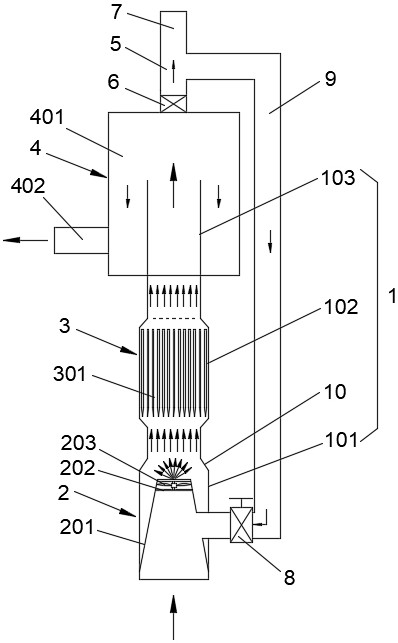
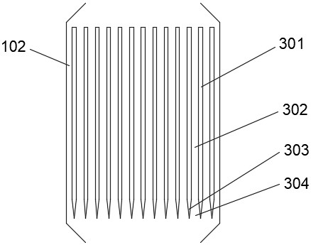
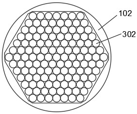
[0019] like Figure 1-Figure 3 As shown, a liquid circuit current blocker includes a liquid flow pipe 1, which is placed vertically and divided into an air inlet section 101, a gas blocking section 102, and a gas separation section 103 in order from bottom to top. The air inlet section 101 is provided with a bubble generating device 2, the air blocking section 102 is provided with a bubble blocking device 3, the gas dividing section 103 is provided with a gas-liquid separation device 4, and the air bubble generating device 2 is provided with an inlet. The air pipe 9 and the air intake regulating valve 8, the air intake pipe 9 is connected ...


PUM


Abstract

The invention discloses a liquid circuit current interrupter, comprising a liquid flow pipe, the liquid flow pipe is placed vertically and divided into an air inlet section, an air choke section and an air separation section in sequence from bottom to top. A bubble generating device is provided in the air blocking section, a bubble blocking device is provided in the air blocking section, a gas-liquid separation device is provided in the gas dividing section, and an air intake pipe and an intake regulating valve are provided in the air bubble generating device. The port is connected to the external inflatable equipment, the top of the gas-liquid separation device is provided with an air outlet, and the air outlet is provided with an air outlet valve and is connected to an air inlet pipe. The present invention has a simple structure and is easy to process. Better blocking effect, reducing the loss caused by bypass current; at the same time avoiding the phenomenon of water hammer and vibration; while realizing the blocking of liquid circuit current, it can shorten the length of the pipeline, save space and cost, and reduce the operating loss and cost of the system. equipment cost.

Description

technical field [0001] The present invention relates to the technical field of liquid flow batteries, in particular to a liquid circuit current interrupter. Background technique [0002] The flow battery has the characteristics of safety, long life, low cost of electricity, fast response speed, fast charging and discharging of large current, and no pollutant emission during operation. It has demonstrated advantages in the application of large-scale energy storage systems such as wind energy, solar energy and other renewable energy power generation, grid peak shaving and valley filling, etc. The charge-discharge efficiency is a key indicator of the battery, and the bypass current is one of the important factors affecting the efficiency of the flow battery system. [0003] There is a bypass current in the electrolyte in the lines of the flow battery system. When the battery is shut down, the bypass current can be cut off by closing the flow valve. During the operation of th...

Claims


Application Information

Patent Timeline
Patent Type & Authority Patents(China)
IPC IPC(8): H01M8/04955H01M8/18
CPCH01M8/04955H01M8/188Y02W10/10
Inventor 熊仁海王宇郭勇
Owner 杭州德海艾科能源科技有限公司
Learn More