
Self-cleaning roof solar panel for new energy automobile

A new energy vehicle and solar panel technology, which is applied in the field of self-cleaning roof solar panels for new energy vehicles, can solve problems affecting the use of solar panels, and achieve the effect of avoiding impurities and water residues

Pending Publication Date: 2022-05-13
曾平
View PDF1 Cites 2 Cited by
  • Summary
  • Abstract
  • Description
  • Claims
  • Application Information

AI Technical Summary

Problems solved by technology

[0003] The Chinese patent with the application number CN201821641087.0 discloses a solar panel for new energy vehicles, which includes a lighting panel, a folding wheel, a connection box and a connecting panel. A lighting strip is fixed on the top of the lighting panel, and the two lighting panels are connected through the rotation of the lighting panel shaft. , There is a handle shaft on the outside of the lighting board, the handle shaft is fixedly connected with the lighting board, the handle ring passes through the inside of the handle shaft and is connected with the handle shaft in rotation, the lower end of the lighting board is fixed with a fixing groove, the lower end of the fixing groove is detachably connected with the fixing block, and the fixing block The lower end is fixedly connected with the connecting plate, the lower end of the connecting plate is fixedly connected with the rotary table, the lower end of the rotary table is fixedly connected with the motor, the two sides of the lower end of the rotary table are connected with the connecting column in rotation, and the lower end of the connecting column is connected with the conductive table in rotation. The device is easy to use and efficient. High, easy to disassemble and install, and easy to carry. Although the above patent can store electricity for the battery of new energy vehicles, there will be a lot of impurities and dust in the solar panel after long-term use, which will easily affect the use of the solar panel.

Method used


Image

  • Self-cleaning roof solar panel for new energy automobile
  • Self-cleaning roof solar panel for new energy automobile
  • Self-cleaning roof solar panel for new energy automobile

Examples


Embodiment 1

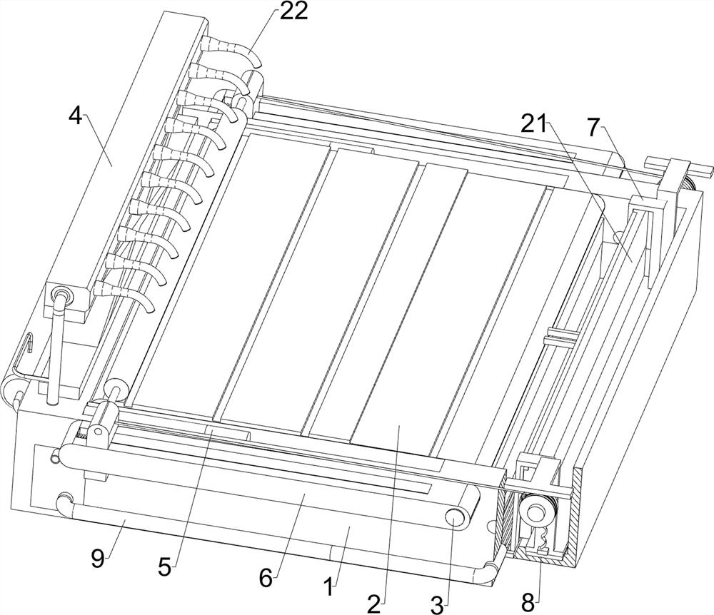
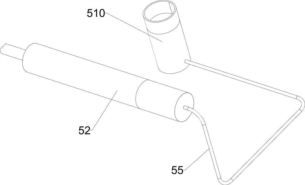
[0039] A self-cleaning roof solar panel for new energy vehicles, including a mounting base 1, a solar panel 2, a partition 21, a nozzle 22, a rotating shaft 3, a flushing mechanism 4 and a jacking mechanism 5, please refer to Figure 1-Figure 7 As shown, the rotating shaft 3 is rotatably connected between the upper right side of the mounting seat 1, and the solar panel 2 is installed in the middle of the rotating shaft 3 by welding. The solar panel 2 is located in the mounting seat 1, and the upper right side of the mounting seat 1 A partition plate 21 is installed between them by welding, and a jacking mechanism 5 is installed between the mounting seat 1 and the left side of the bottom of the solar panel 2. When the jacking mechanism 5 is in operation, the jacking mechanism 5 can drive the solar panel 2 It swings upwards in an inclined state. A flushing mechanism 4 is installed on the left part of the mounting base 1. Ten nozzles 22 are evenly spaced on the flushing mechanism ...

Embodiment 2

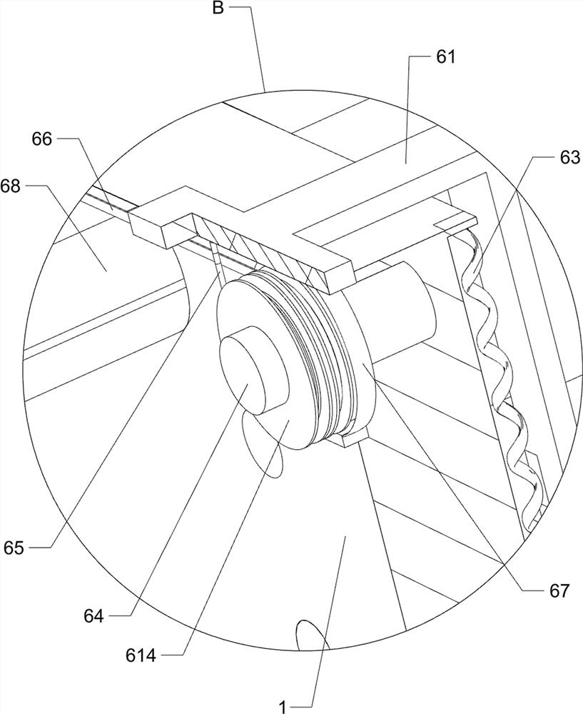
[0046] On the basis of embodiment 1, also includes cleaning mechanism 6, and cleaning mechanism 6 includes u-shaped frame 61, projection 62, second spring 63, rotating shaft 64, stay wire 65, stay cord 66, scroll spring 67, Turret 68, stop block 69, mounting block 610, third spring 611, mounting bar 612, roller 613 and double groove reel 614, see figure 1 , figure 2 , Figure 8 , Figure 9 with Figure 10 As shown, the front and rear sides of the rotating shaft 3 are connected with a turret 68 by welding, and the top of the turret 68 is slidably connected with a mounting block 610. The third spring 611 is installed in the middle by welding, the upper part of the front and rear mounting blocks 610 is rotatably connected with the installation rod 612, and the middle part of the installation rod 612 is fixed with a roller 613 along the circumferential direction, and the roller 613 is connected with the solar panel. 2 contacts, when the roller 613 moves to the right, the roll...

Embodiment 3

[0051] On the basis of Embodiment 1 and Embodiment 2, an auxiliary floating mechanism 8 is also included, and the auxiliary floating mechanism 8 includes a fixed frame 81 and a columnar air bag 82, please refer to figure 2 , Figure 14 with Figure 15 As shown, a fixed frame 81 is installed on the inner bottom of the U-shaped frame 61 by means of bolt connection, and nine columnar airbags 82 are evenly spaced between the left and right sides of the fixed frame 81 .

[0052] Also include a return mechanism 9, the return mechanism 9 includes a return pipe 91 and a filter screen 92, please refer to figure 1 , figure 2 , Figure 16 with Figure 17 As shown, the water storage tank 41 is connected with a return pipe 91 on the right side of the lower part of the front and rear sides. A filter screen 92 is installed in the connected mode, and the filter screen 92 can remove impurities in the water.

[0053] When the water for removing impurities and dust falls into the mountin...


PUM


Abstract

The invention relates to a roof solar panel, in particular to a self-cleaning roof solar panel for a new energy automobile. The self-cleaning roof solar panel for the new energy automobile can remove impurities and dust on the solar panel and does not affect use of the solar panel. A self-cleaning roof solar panel for a new energy automobile comprises a mounting base, a solar panel and a rotating shaft, the rotating shaft is rotatably connected between the right sides of the upper portions of the front side and the rear side of the mounting base in a penetrating mode, and the solar panel is fixedly connected to the middle of the rotating shaft. When the solar panel is used for a long time and has a large amount of impurities and dust, the flushing mechanism is started, the flushing mechanism operates to discharge water into the jacking mechanism, the jacking mechanism operates to drive the solar panel to swing upwards to a proper position, the flushing mechanism further discharges water into the spray head, and the spray head sprays the water onto the solar panel. And impurities and dust on the solar panel are removed by water, so that the use of the solar panel can be prevented from being influenced by residual impurities and dust.

Description

technical field [0001] The invention relates to a roof solar panel, in particular to a self-cleaning roof solar panel for a new energy vehicle. Background technique [0002] In the manufacturing process of new energy vehicles, a large number of spare parts are generally used, but solar panels are one of the necessary components. Solar panels can convert sunlight into electrical energy, which also stores electricity for the batteries of new energy vehicles. . [0003] The Chinese patent with the application number CN201821641087.0 discloses a solar panel for new energy vehicles, which includes a lighting panel, a folding wheel, a connection box and a connecting panel. A lighting strip is fixed on the top of the lighting panel, and the two lighting panels are connected through the rotation of the lighting panel shaft. , There is a handle shaft on the outside of the lighting board, the handle shaft is fixedly connected with the lighting board, the handle ring passes through th...

Claims


Application Information

Patent Timeline
Patent Type & Authority Applications(China)
IPC IPC(8): H02S40/10
CPCH02S40/10Y02E10/50
Inventor 曾平
Owner 曾平
Learn More