Supercharge Your Innovation With Domain-Expert AI Agents!

Cold box pre-cooling equipment for natural gas liquefaction in chemical industry

A natural gas and cold box technology, applied in liquefaction, mechanical equipment, refrigeration and liquefaction, etc., can solve the problems of not collecting excess hot gas, environmental pollution, etc., to avoid affecting the environment and avoiding blockage.

Active Publication Date: 2022-05-17
广州兴丰能源科技有限公司
View PDF10 Cites 0 Cited by
  • Summary
  • Abstract
  • Description
  • Claims
  • Application Information

AI Technical Summary

Problems solved by technology

[0004] In order to overcome the disadvantages that the current liquefied natural gas cold box does not have the function of collecting excess hot gas, and the excess hot gas is directly discharged to the outside, thus causing certain pollution to the environment, the technical problem is: to provide a natural gas liquefaction device for chemical industry that will not affect the environment Cold box precooling equipment

Method used


Image

  • Cold box pre-cooling equipment for natural gas liquefaction in chemical industry
  • Cold box pre-cooling equipment for natural gas liquefaction in chemical industry
  • Cold box pre-cooling equipment for natural gas liquefaction in chemical industry

Examples


Embodiment 1

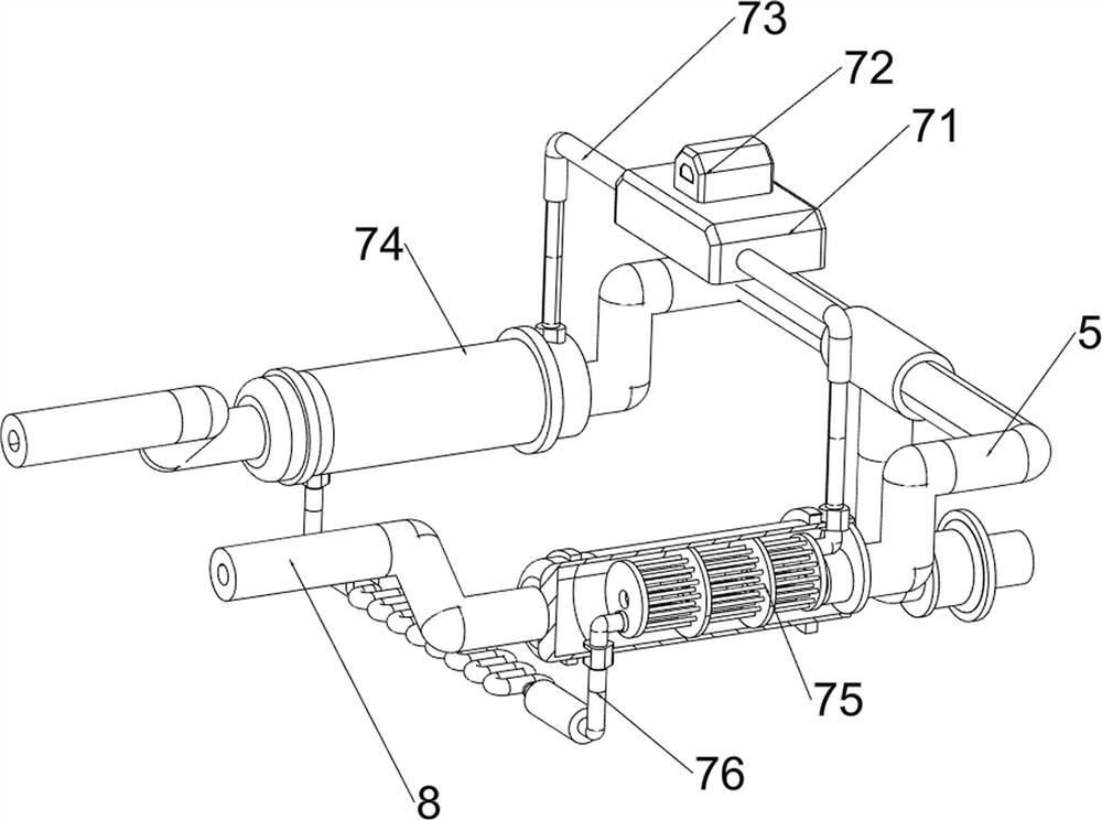
[0090] A cold box precooling equipment for chemical natural gas liquefaction, such as figure 1 , figure 2 , image 3 , Figure 4 , Figure 5 , Figure 6 , Figure 7 , Figure 9 , Figure 14 and Figure 15 As shown, it includes a cold box 1, an intake pipe 2, a mounting base 3, a compressor 4, a first pipeline 5, a filter mechanism 6, a heat exchange mechanism 7, a first exhaust pipe 8 and a water cooling mechanism 10, and the left side of the cold box 1 The lower part of the side is connected with the intake pipe 2, the left side of the cold box 1 is connected with the mounting base 3, the intake pipe 2 is connected with the bottom of the mounting base 3, the right side of the mounting base 3 is connected with the compressor 4, and the right side of the compressor 4 is connected with the first Pipeline 5, filter mechanism 6 is provided on the lower left side of cold box 1, heat exchange mechanism 7 is arranged on the first pipeline 5, first exhaust pipe 8 is connected...

Embodiment 2

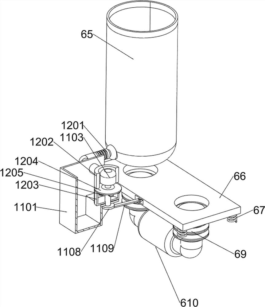
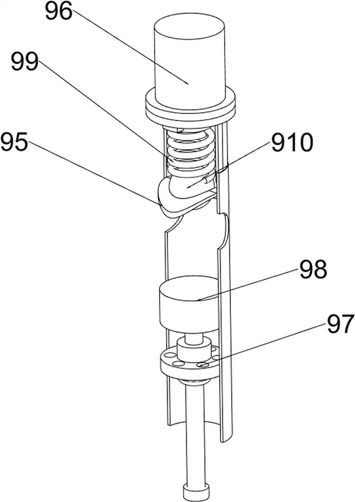
[0096] On the basis of Example 1, such as image 3 , Figure 4 , Figure 5 , Figure 6 , Figure 7 , Figure 8 , Figure 10 , Figure 11 , Figure 12 and Figure 13 As shown, a refrigeration mechanism 9 is also included, and the refrigeration mechanism 9 includes a pressure vessel 91, a third pipeline 92, a condensation pipeline 93, a liquid nitrogen container 94, a fourth pipeline 95, a refrigeration pipeline 96, a first fixed block 97, a push block 98. The fourth spring 99 and the blocking block 910. A pressure vessel 91 is installed on the outside of the circulation pipe 76. The middle part on the right side of the pressure vessel 91 is connected to a third pipeline 92. The left side of the third pipeline 92 is connected to a condensation pipeline 93. The bottom of the condensation pipeline 93 The end is connected to the top of the pressure vessel 91, the top of the third pipeline 92 is connected to the fourth pipeline 95, the top of the third pipeline 92 is connect...


PUM


Abstract

The invention relates to pre-cooling equipment, in particular to cold box pre-cooling equipment for natural gas liquefaction for chemical engineering. The technical problem is to provide the cold box pre-cooling equipment for natural gas liquefaction for chemical engineering, which does not affect the environment. Cold box pre-cooling equipment for natural gas liquefaction for chemical engineering comprises a cold box and a gas inlet pipe, and the gas inlet pipe is fixedly connected to the lower portion of one side of the cold box; the mounting seat is fixedly connected to one side of the inner wall of the cold box, and the air inlet pipe is fixedly connected with the mounting seat; and the compressor is mounted on the mounting seat. The filtering mechanism can filter air, dust in the air is prevented from entering the compressor, the compressor can cool the air, the heat exchange mechanism can also cool the air, and therefore the environment in the cold box is refrigerated, the water cooling mechanism can cool redundant hot air, and the cooling efficiency is improved. Redundant hot air is prevented from being directly discharged to the outside, and the environment is prevented from being influenced.

Description

technical field [0001] The invention relates to a precooling device, in particular to a cold box precooling device for chemical natural gas liquefaction. Background technique [0002] Natural gas is a naturally occurring gas in nature. It is colorless, odorless, and non-toxic. In the chemical industry, liquefied natural gas cold boxes are often used to exchange heat between natural gas and refrigerants. The current liquefied natural gas cold box is in the cooling process. , will produce some excess hot gas, but the current liquefied natural gas cold box does not have the function of collecting excess hot gas, and the excess hot gas is directly discharged to the outside, thus causing certain pollution to the environment. [0003] In response to the current problems, we design a device that will not affect the environment. Contents of the invention [0004] In order to overcome the disadvantages that the current liquefied natural gas cold box does not have the function of c...

Claims


Application Information

Patent Timeline
Patent Type & Authority Applications(China)
IPC IPC(8): F25J1/02F25J5/00F04B39/16
CPCF25J1/0228F25J5/00F04B39/16F25J2210/62
Inventor 赖世安
Owner 广州兴丰能源科技有限公司
Features
  • R&D
  • Intellectual Property
  • Life Sciences
  • Materials
  • Tech Scout
  • Unparalleled Data Quality
  • Higher Quality Content
  • 60% Fewer Hallucinations
Learn More