Quantitative feeding equipment for processing environment-friendly thermosetting powder coating

A thermosetting powder and coating technology, applied in the fields of plastic recycling, recycling technology, grain processing, etc., can solve the problems of inability to control the feeding weight, inconvenient use, and inconvenient feeding of environmentally friendly thermosetting powder coatings.

Pending Publication Date: 2022-05-20
德清亮彩塑粉有限公司
View PDF18 Cites 0 Cited by
  • Summary
  • Abstract
  • Description
  • Claims
  • Application Information

AI Technical Summary

Problems solved by technology

[0003] 1. Before the environmental protection thermosetting powder coating is fed, there will be granular coatings in the raw materials, which is not convenient to crush the granular environmental protection thermosetting powder coatings, which makes it difficult to feed the environmental protection thermosetting powder coatings;
[0004] 2. After the environmental protection thermosetting powder coating is mixed, the weight of the feeding material cannot be controlled, which makes it more inconvenient to use

Method used


Image

  • Quantitative feeding equipment for processing environment-friendly thermosetting powder coating
  • Quantitative feeding equipment for processing environment-friendly thermosetting powder coating
  • Quantitative feeding equipment for processing environment-friendly thermosetting powder coating

Examples


Embodiment 1

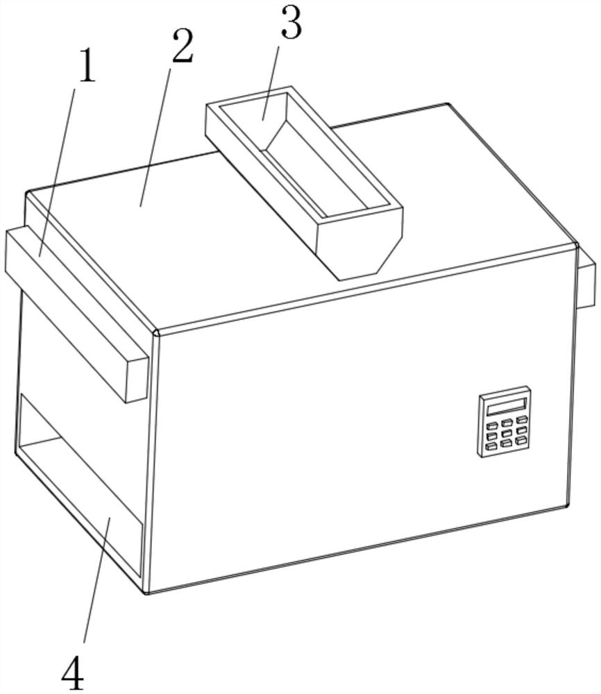
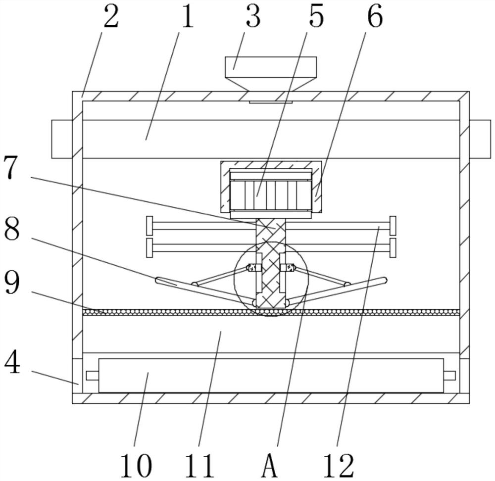
[0034] as Figure 1-5As shown, the present invention provides an environmentally friendly thermoset powder coating processing for quantitative feeding equipment, comprising a feeding box 2, an inlet hopper 3, an outlet 4 and a collection silo 10, the top of the feeding box 2 is embedded with an inlet hopper 3, the left and right sides of the feeding box 2 are opened with an outlet 4, the inner wall of the discharge port 4 slides connected to the collection bin 10, the inner wall of the feeding box 2 and located directly below the feed hopper 3 is provided with a particle crushing frame 1, the left and right ends of the particle crushing frame 1 are inserted through the left and right sides of the outer wall of the feeding box 2, The inner wall of the feeding box 2 is fixed to be connected to the dust cover 6, the inner wall of the dust cover 6 is fixed with a drive motor 5, the drive end of the drive motor 5 is fixed to be connected to the hinge 7, and the outer wall of the hinge 7...

Embodiment 2

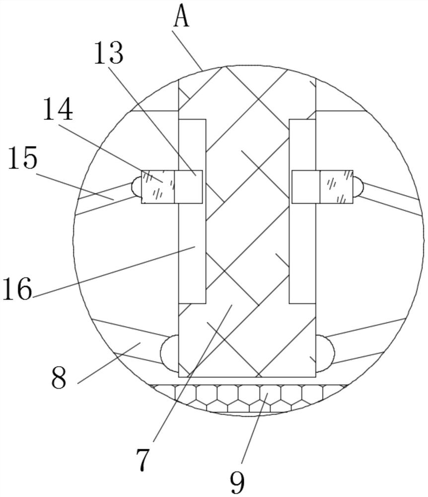
[0038] as Figure 1-5As shown, on the basis of Example 1, the present invention provides a technical solution: preferably, the outer wall of the hinge 7 is hinged at the bottom edge of the outer wall of the adjustment rod 8, the outer wall sliding connection of the hinge 7 is connected to the active ring 14, the outer wall of the moving ring 14 is articulated with a connecting rod 15, the other end of the connecting rod 15 is articulated with the outer wall of the adjustment rod 8, the activity ring 14 when sliding, can be adjusted by means of the connecting rod 15 to the angle between the adjustment rod 8 and the shaft 7, the outer wall of the hinge 7 is opened with a slip groove 16, The inner wall sliding connection of the chute 16 is connected to the sliding block 13, the side of the sliding block 13 is fixedly connected to the inner wall of the moving ring 14, the chute 16 can facilitate the sliding block 13, so that the moving ring 14 can slide down steadily.

Embodiment 3

[0040] as Figure 1-5 As shown, on the basis of Example 1, the present invention provides a technical solution: preferably, the inner wall of the quantitative box 11 is fixed connected to the support frame 32, the top of the support frame 32 is fixed to be connected to the elastic member 29, the top fixed connection to the top of the elastic member 29 is connected to the connecting strip 25, the inner wall side of the connecting strip 25 is fixed connected to the storage hopper 26, the connecting strip 25 and the elastic member 29 are located symmetrically on both sides of the storage hopper 26 symmetrically set, the inner wall of the stock hopper 26 is fixed connected to the support plate 30, The inner wall of the stock hopper 26 is articulated with a flip plate 27, one end of the flip plate 27 is overlapped with the top of the support plate 30, the other end of the flip plate 27 is sliding with the inner wall of the stock hopper 26, the flip plate 27 can be supported by the suppo...


PUM


Abstract

The invention discloses quantitative feeding equipment for environment-friendly thermosetting powder coating processing, and relates to the technical field of quantitative feeding equipment.The quantitative feeding equipment comprises a feeding box, a feeding hopper, discharging ports and a collecting bin, the feeding hopper is fixedly installed at the top of the feeding box in an embedded mode, and the discharging ports are formed in the left side face and the right side face of the feeding box correspondingly; and the inner wall of the discharging opening is slidably connected with a collecting bin, and a particle smashing frame is arranged on the inner wall of the feeding box and located under the feeding hopper. According to the environment-friendly thermosetting powder coating grinding device, through cooperation of the arranged grinding frame, the arranged grinding plate, the arranged material distributing plate, the arranged smashing strips, the arranged electric telescopic rod and the arranged limiting baffle, the falling environment-friendly thermosetting powder coating can be guided through the material distributing plate, the electric telescopic rod can push the grinding frame in a reciprocating mode, and then the arranged smashing strips on the material distributing plate make contact with the grinding plate; and therefore, the granular environment-friendly thermosetting powder can be crushed, falling of the environment-friendly thermosetting powder is facilitated, and the grinding frame can be limited through a limiting baffle.

Description

Technical field [0001] The present invention relates to the technical field of quantitative feeding equipment, specifically to a kind of environmentally friendly thermoset powder coating processing with quantitative feeding equipment. Background [0002] Powder coating refers to a new type of solvent-free 100% solid powder coating, thermosetting powder coating is composed of thermosetting resin, curing agent, pigment, filler and additive. It has the characteristics of no solvent pollution, 100% film formation and low energy consumption. The following issues exist with existing technologies: [0003] 1, environmental protection thermoset powder coating before feeding, there will be granular coating in the raw material, it is not convenient to crush the granular environmental protection thermoset powder coating, resulting in environmentally friendly thermoset powder coating is not easy to feed; [0004] 2. After mixing, environmentally friendly thermoset powder coatings cannot cont...

Claims


Application Information

Patent Timeline
IPC IPC(8): B02C1/00B02C23/02B02C23/00B02C23/10B29B13/10
CPCB02C1/00B02C23/02B02C23/00B02C23/10B29B13/10Y02W30/62
Inventor 胡雪平
Owner 德清亮彩塑粉有限公司
Why Eureka
Try Eureka