Circuit board repairing method based on movable induction heating

A technology of induction heating and circuit board, applied in the direction of electric heating devices, metal processing equipment, process efficiency improvement, etc., can solve problems such as missed installation or falling off, increased production cost, waste of raw materials, etc., to achieve sufficient heat and good heating effect , High repair efficiency

Pending Publication Date: 2022-05-20
广东粤灿半导体设备有限公司
View PDF0 Cites 2 Cited by
  • Summary
  • Abstract
  • Description
  • Claims
  • Application Information

AI Technical Summary

Problems solved by technology

[0003] With the development of electronic technology and the progress of packaging technology, the circuit scale is getting larger and larger, the circuit layout is getting more and more compact, the volume of individual electronic components is getting smaller and smaller, and the electronic components that need to be soldered on a single substrate are also becoming more and more The spacing between adjacent electronic components is getting smaller and smaller, and the processing accuracy of the circuit board manufacturing process is also getting higher and higher. It is for the same reason that after a single circuit board is formed once, the local area Individual electronic components due to their own faults or processing errors, the probability of component damage, offset, miss

Method used


Image

  • Circuit board repairing method based on movable induction heating
  • Circuit board repairing method based on movable induction heating

Examples


Embodiment Construction

[0046] In order to make the object, technical solution and advantages of the present invention clearer, the present invention will be further described in detail below in conjunction with the accompanying drawings and embodiments. It should be understood that the specific embodiments described here are only used to explain the present invention, not to limit the present invention.

[0047] To achieve the above object, the technical scheme of the present invention is as follows:

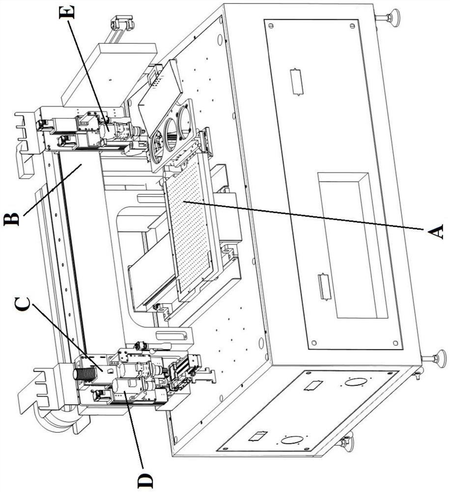
[0048] see Figure 1-2 .

[0049] In this specific embodiment, an active heating circuit board rework method is provided. This wafer rework method is applied to Mini LED or Micro LED displays. When a partial fault occurs on the display circuit board, it is necessary to remove the faulty single R, After the G and B light-emitting elements, re-weld the new R, G, and B light-emitting elements that have the same function as the original R, G, and B light-emitting elements.

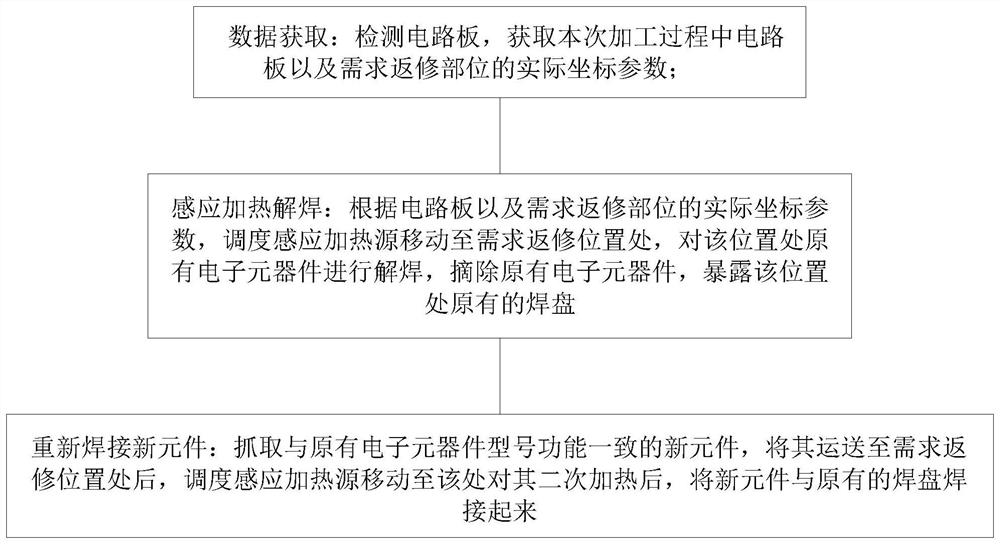
[0050] The repair method is...


PUM


Abstract

The invention discloses a movable heating circuit board repair method, which comprises the steps of S1, data acquisition, S2, induction heating desoldering, S3, new element resoldering and the like. The movable heating circuit board repair method has the advantages of being flexible in machining, high in repair efficiency, high in repair success rate, wide in machining coverage, high in adaptability, sufficient in heat, high in heat source controllability, capable of meeting the desoldering or welding requirements of elements in a wide size range, capable of well achieving the expected heating effect, accurate in positioning, high in repair efficiency, high in repair efficiency, high in repair success rate and high in heat source controllability. And the work is stable.

Description

technical field [0001] The invention belongs to the technical field of precision machining, and in particular relates to a circuit board repairing machine. Background technique [0002] The circuit board is often composed of a substrate, solder and electronic components. After the circuit is designed, the circuit part of the circuit is printed on the substrate. For the position of the electronic components in the circuit design, it is necessary to reserve a pad on the substrate. , when manufacturing, move the specified components to their corresponding positions, and put their metal pads one by one to the pads on the substrate. After applying solder on the pads, heat the solder with a designated heat source to melt it. The solder adheres the electronic components to the pads, and the electronic components are thus connected to the substrate to complete the soldering process of the circuit board. [0003] With the development of electronic technology and the progress of pack...

Claims


Application Information

Patent Timeline
IPC IPC(8): B23K1/018B23K1/002B23K3/047B23K3/08
CPCB23K1/018B23K1/002B23K3/0475B23K3/08Y02P10/25
Inventor 王双玲赵坤黄饮智赵鹏
Owner 广东粤灿半导体设备有限公司
Why Eureka
Try Eureka