Silicon rod cutting equipment and silicon rod cutting method

A silicon rod and equipment technology, applied in the field of silicon rod cutting equipment, can solve the problems of complex equipment structure, low cutting precision, inflexible operation, etc., to reduce production costs, improve cutting efficiency, and avoid the effect of ripples

Pending Publication Date: 2022-05-20
TDG NISSIN PRECISION MACHINERY CO LTD
View PDF9 Cites 1 Cited by
  • Summary
  • Abstract
  • Description
  • Claims
  • Application Information

AI Technical Summary

Problems solved by technology

[0004] In view of the shortcomings of the above-mentioned related technologies, the purpose of this application is to disclose a silicon rod cutting device and a silicon rod cutting method, which are used to solve the problems in the related technology such as complicated equipment structure, inflexible operation and low cutting accuracy.

Method used


Image

  • Silicon rod cutting equipment and silicon rod cutting method
  • Silicon rod cutting equipment and silicon rod cutting method
  • Silicon rod cutting equipment and silicon rod cutting method

Examples


Embodiment Construction

[0051] The implementation of the present application will be described by specific specific examples below, and those skilled in the art can easily understand other advantages and effects of the present application from the content disclosed in this specification.

[0052] In the following description, several embodiments of the present application are described with reference to the accompanying drawings. It is to be understood that other embodiments may be utilized, and mechanical, structural, and operational changes may be made without departing from the spirit and scope of the present disclosure. The following detailed description should not be considered limiting, and the scope of the embodiments of the present application is defined only by the claims of the issued patent. The terminology used herein is for describing particular embodiments only and is not intended to limit the application. Spatially relative terms such as "upper", "lower", "left", "right", "below", "be...


PUM


Abstract

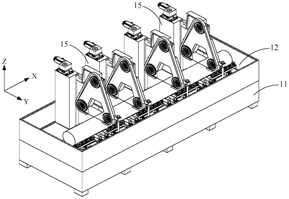
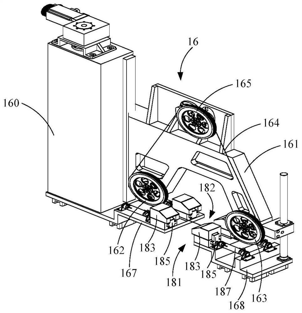
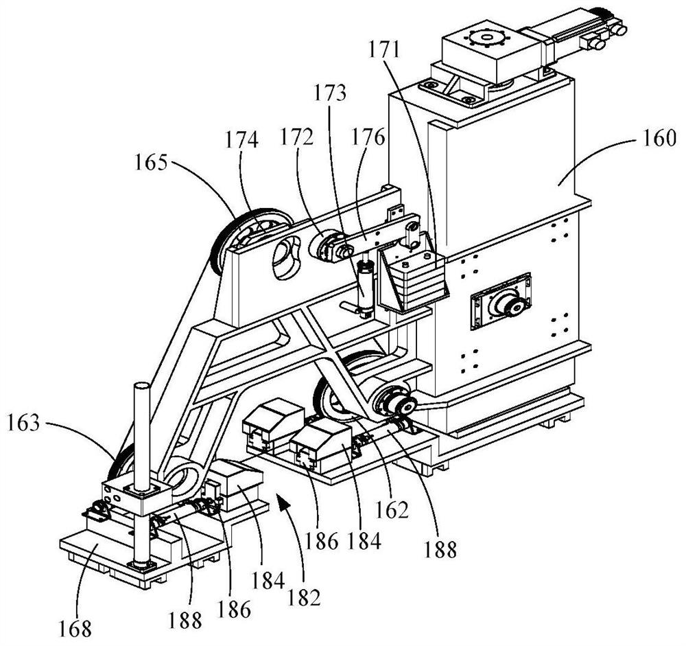
The invention discloses silicon rod cut-off equipment and a silicon rod cut-off method.The silicon rod cut-off equipment comprises a machine base, a material conveying table and at least two wire cutting devices, the at least two wire cutting devices are mutually independent, and therefore cut-off operation can be carried out on silicon rods to be cut on the material conveying table through the independent wire cutting devices; and the operation freedom degree and the cutting efficiency in the silicon rod cutting operation are improved. The linear cutting unit in the linear cutting device adopts the closed-loop cutting line, so that high-speed running of the cutting line can be kept, the cutting efficiency is improved, meanwhile, the closed-loop cutting line can run in the same running direction in the cutting-off operation, and therefore, the linear cutting unit can realize high-precision cutting-off operation, and the cutting efficiency is improved. According to the closed-loop cutting line, the problem that ripples exist on the cutting face due to operation reversing or operation speed of the cutting line in an existing cutting mode is solved, meanwhile, the total length of the cutting line needed by the linear cutting unit can be effectively reduced, parts such as a take-up barrel and a pay-off barrel are omitted, and the production cost is reduced.

Description

technical field [0001] The present application relates to the technical field of silicon workpiece processing, in particular to a silicon rod cutting device and a silicon rod cutting method. Background technique [0002] Wire cutting technology is currently the most advanced silicon material processing technology in the world. Its principle is that the high-speed running steel wire drives the cutting edge attached to the steel wire or directly uses diamond wire to rub the workpiece to be processed, so as to achieve wire cutting. the goal of. During the cutting process, the steel wire or diamond wire is guided by the guide wheel, and a cutting wire saw or a wire net is formed on the cutting wheel, and the workpiece to be processed is raised and lowered by the worktable or the cutting wire saw or the wire net is raised The lowering realizes the feeding of the workpiece. Under the action of the pressure pump, the cooling water automatic spraying device assembled on the equipm...

Claims


Application Information

Patent Timeline
IPC IPC(8): B28D5/04B28D7/04B28D7/00
CPCB28D5/045B28D5/0082B28D5/0058B28D7/04B28D5/04B28D7/00B28D7/02
Inventor 卢建伟金晔天潘雪明朱勤超
Owner TDG NISSIN PRECISION MACHINERY CO LTD
Why Eureka
Try Eureka