Al technical title is built by PatSnap Al team. It summarizes the technical point description of the patent document.
A tool box and assembly technology, which is applied in mining equipment, tunnels, earthwork drilling, etc., can solve the problems of economic property, personal safety loss, different tool wear conditions, crisis tool head structural stability, etc., and achieve reduction The risk of failure, the reduction of positive pressure, and the effect of reliable device structure
Pending Publication Date: 2022-05-20
YINGNUOWEI VALVE IND
View PDF0 Cites 0 Cited by
Summary
Abstract
Description
Claims
Application Information
AI Technical Summary
This helps you quickly interpret patents by identifying the three key elements:
Problems solved by technology
Method used
Benefits of technology
Problems solved by technology
With the increase of river crossing, river crossing and subsea tunnel construction projects, the geological conditions and construction technology are becoming more and more difficult. The speed will drop, and the torque of the cutter head will continue to increase, which will seriously affect the efficiency of construction operations and endanger the structural stability of the cutter head
If the method of opening the cabin is not adopted to carry out inspection and replacement of knives, it is easy to cause huge losses in economic property, personal safety, etc.
[0004] At present, the tools are often worn and damaged after being used for a period of time. The tools on the same tool box are fixed on the same spindle, and they can only be replaced uniformly when they are replaced. However, the wear of each tool is different. Discrimination
Method used
Image
Click on the blue label to locate the original text in one second.
Reading with bidirectional positioning of images and text.
Examples
Embodiment Construction
[0028]The following will be combined with the accompanying drawings in the embodiments of the present invention, the technical solution in the embodiments of the present invention will be described clearly and completely, it is clear that the embodiments described are only a part of the embodiment of the present invention, not all embodiments. Based on embodiments in the present invention, all other embodiments obtained by those of ordinary skill in the art without paying creative labor, are within the scope of protection of the present invention.
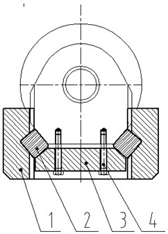
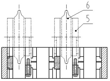
[0029] as Figure 1-4 As shown, a four-way toolbox assembly comprises a knife box part and a hob part; the knife box portion comprises a knife box body 1, a central wedge 2, a center tensioning block 3, a high-strength bolt 4 composition. The hob part is an end cover type single body hob, only involves the shape of the ring 6 and the end cover support seat 5 and other external parts, does not involve the internal structure of the hob. T...
PUM
Abstract
A quadruple cutter box assembly comprises a cutter box part and a hob part. The cutter box part comprises a cutter box body, a center tensioning block, a center wedge block and a bolt. The hobbing cutter part is an end cover type single hobbing cutter, only relates to appearance parts such as a cutter ring and an end cover supporting seat, and does not relate to the internal structure of the hobbing cutter, the end cover type single hobbing cutter is fixed on the cutter box body through a central tensioning block, a central wedge block and a plurality of high-strength bolts, and the four end cover type single hobbing cutters on the quadruple cutter box assembly are mutually independent; and different extension lengths can be realized through different heights of the central wedge block. V-shaped clamping grooves matched with the center wedge blocks are formed in the middle positions of the two sides of the cutter box body, the center wedge blocks are installed in the V-shaped clamping grooves, the center tensioning block and the end cover supporting base are pressed on the center wedge blocks through high-strength bolts, the included angle of the V-shaped grooves is alpha, the included angle between the pressure-bearing face and the vertical face of each V-shaped groove is beta, and the included angle alpha and the included angle beta are selected to be proper values. The bearing pressure can be effectively reduced, and the bearing capacity of the hob is improved.
Description
Technical field [0001] The present invention relates to the technical field of shield machine, specifically to a quad knife box assembly and hob assembly on the cutterhead of a large shield machine. Background [0002] Shield machine is a kind of tunnel boring special engineering machinery, modern shield boring machine set light, machine, electricity, liquid, sensing, information technology in one, with excavation and cutting of soil, transport ballast, assembly tunnel lining, measurement guidance correction and other functions, involving geology, civil engineering, machinery, mechanics, hydraulics, electrical, control, measurement and other disciplines of technology, and according to different geology for "tailor-made" design and manufacturing, reliability requirements are extremely high. [0003] At present, shield tunnel construction is widely used in the construction of urban subway and highway tunnels. With the increase of cross-river, cross-river and submarine tunnel constr...
Claims
Application Information
Patent Timeline
Application Date:The date an application was filed.
Publication Date:The date a patent or application was officially published.
First Publication Date:The earliest publication date of a patent with the same application number.
Issue Date:Publication date of the patent grant document.
PCT Entry Date:The Entry date of PCT National Phase.
Estimated Expiry Date:The statutory expiry date of a patent right according to the Patent Law, and it is the longest term of protection that the patent right can achieve without the termination of the patent right due to other reasons(Term extension factor has been taken into account ).
Invalid Date:Actual expiry date is based on effective date or publication date of legal transaction data of invalid patent.