
Heat dissipation device and method for oil-immersed electrical equipment without moving parts

A technology for electrical equipment and heat dissipation devices, applied in the field of heat dissipation method design for electrical equipment, can solve problems such as large oil flow velocity, increased particle size, and increased risk of partial discharge, etc., to reduce flow velocity and save flow channels , The effect of reducing the risk of foreign matter mixing

Pending Publication Date: 2022-05-20
浙江大学嘉兴研究院 +1
View PDF6 Cites 0 Cited by
  • Summary
  • Abstract
  • Description
  • Claims
  • Application Information

AI Technical Summary

Problems solved by technology

The cooling method of strong oil air cooling uses the submersible oil pump as the main power component, which drives the transformer oil to flow out from the transformer box into the refrigeration system and then returns to the transformer box, which makes the entire cooling cycle have a large oil flow rate. This also increases the probability of foreign matter in the transformer oil and the risk of foreign matter entering key parts of the transformer and causing partial discharge
Existing test results have shown that submersible pump shut down due to foreign matter entering the shaft, submersible pump blades break / fall off, and repeated circulation of transformer oil causes the particle size in the oil to increase, etc., which are some common failure forms of transformers.

Method used


Image

  • Heat dissipation device and method for oil-immersed electrical equipment without moving parts
  • Heat dissipation device and method for oil-immersed electrical equipment without moving parts
  • Heat dissipation device and method for oil-immersed electrical equipment without moving parts

Examples


Embodiment Construction

[0026] The specific implementation manners of the embodiments of the present invention will be described in detail below in conjunction with the accompanying drawings. It should be understood that the specific implementation manners described here are only used to illustrate and explain the embodiments of the present invention, and are not intended to limit the embodiments of the present invention.

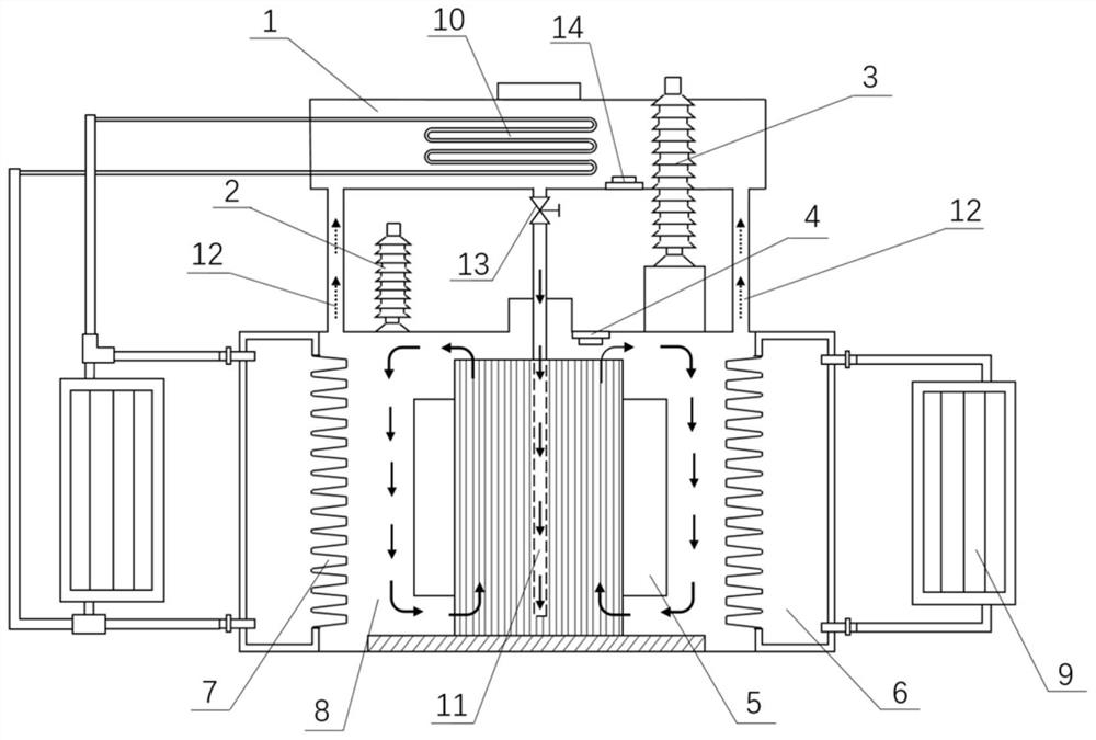
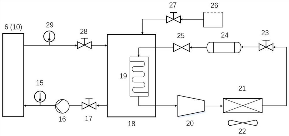
[0027] On the one hand, the present invention provides an oil-immersed heat dissipation device for electrical equipment without moving parts, such as figure 1 As shown, the device provided in this embodiment includes: a cooling cavity 6, a place for cold water circulation, which takes away the heat of the transformer interior 8, and a coil 5 is installed in the transformer interior 8; the fin 7 structure on the surface of the cooling cavity 6 can Replace the fin structure according to different heat dissipation requirements; the first oil temperature detection device 4 obtains the...


PUM


Abstract

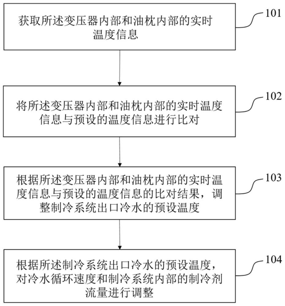
The invention discloses an oil-immersed electrical equipment heat dissipation device and method without moving parts, and the method comprises the steps: arranging two water cooling cavities at the two sides of a transformer, and cooling the transformer oil in the transformer through the water cooling cavities; the refrigerating system provides cooling water for the water cooling cavity and recovers warm water after heat exchange; real-time temperature data in the transformer is obtained, the real-time temperature data is compared with preset temperature information, and the preset temperature of cold water at an outlet of the refrigerating system is adjusted according to the comparison result of the real-time temperature information in the transformer and the preset temperature information; and according to the preset temperature of the cold water at the outlet of the refrigerating system, the cold water circulation speed and the refrigerant flow in the refrigerating system are adjusted. On the premise that the heat dissipation requirement is met, a runner of the radiator is omitted, the oil flow speed in the transformer is greatly reduced, and therefore the risk that foreign matter exists in transformer oil is reduced, and the probability that particles in the oil enter key parts of the transformer is reduced.

Description

technical field [0001] The invention relates to the field of heat dissipation method design for electrical equipment, in particular to an oil-immersed electrical equipment heat dissipation device and method without moving parts. Background technique [0002] The transformer plays a very important role in the power system, and its safe operation is closely related to whether the power grid can operate efficiently and safely. Once a transformer fails, it will bring huge economic losses to the power grid and have a huge impact on people's lives. In order to ensure the long-term safe and reliable operation of the transformer, the temperature of the transformer must be controlled within a certain range. At present, the common heat dissipation method of oil-immersed transformers is fin radiator. For some transformers with higher voltage levels, strong oil air cooling is required to meet the heat dissipation requirements. The cooling method of strong oil air cooling uses the subm...

Claims


Application Information

Patent Timeline
IPC IPC(8): H01F27/14H01F27/16
CPCH01F27/14H01F27/16Y02B30/70
Inventor 黄钰期陈海鹏张鹏飞杨康博吴焱
Owner 浙江大学嘉兴研究院
Learn More