Adjusting tool for machining lathe claw

A lathe and tooling technology, used in metal processing equipment, metal processing mechanical parts, manufacturing tools, etc., to achieve the effect of improving dimensional accuracy, improving sliding smoothness, and precise tool feeding

Pending Publication Date: 2022-05-24
HANGZHOU DAHE THERMO MAGNETICS CO LTD
View PDF17 Cites 0 Cited by
  • Summary
  • Abstract
  • Description
  • Claims
  • Application Information

AI Technical Summary

Problems solved by technology

[0008] Aiming at the problem in the prior art that when manufacturing lathe jaws of different specifications, it is necessary to separately prepare and fix the tooling of the specification

Method used


Image

  • Adjusting tool for machining lathe claw
  • Adjusting tool for machining lathe claw
  • Adjusting tool for machining lathe claw

Examples


Embodiment 1

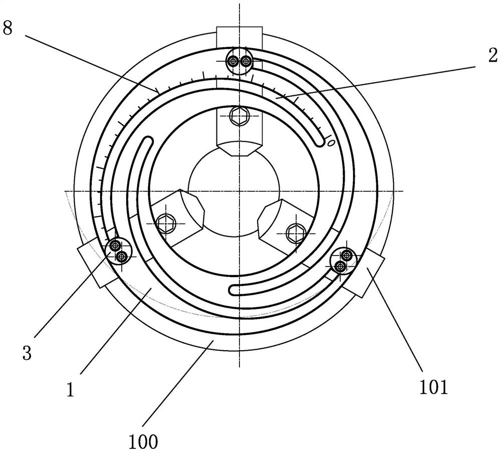
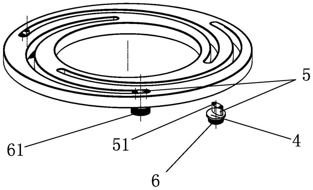
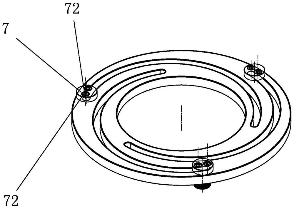
[0028] like figure 1 , 2 As shown in the figure, an adjusting tool for processing lathe jaws includes an adjustable base plate 1 arranged on the main shaft 100 of the equipment. The adjustable base plate 1 is provided with a chute group, and the chute group includes at least two radians. Gradient chute 2, the chute 2 of the chute group is arranged symmetrically along the center of the adjustable base plate 1; wherein, each chute 2 is slidably provided with a tooling slider 3, and the bottom of the tooling slider 3 can be slidably arranged. Connect the jaws 101 of the lathe to be processed. The chute 2 is arranged in an involute with the center of the adjustable base plate 1 as the center. The equipment main shaft 100 is provided with a guide rail, and the claw 101 of the lathe to be processed moves in the guide rail along the radial direction of the equipment main shaft 100 .

[0029]The radian of the chute 2 of the chute group is gradual. When the operator rotates the adju...

Embodiment 2

[0035] like Figure 5 As shown, the difference from Embodiment 1 is that in this embodiment, the main shaft 100 of the equipment is of a horizontal structure, the adjustable base plate 1 is arranged on the side of the main shaft 100 of the equipment, and the claw 101 of the lathe to be processed is under the limit of the tooling slider 3 The radial direction deviation will not be generated due to gravity, and the radial distance is always accurately adjusted with the rotation angle of the adjustable base plate 1. It can be seen from this embodiment that the tooling provided by the present invention is used in the vertical spindle and the horizontal spindle. can be used normally.


PUM


Abstract

The adjusting tool for machining the lathe claw comprises an adjustable base disc arranged on an equipment spindle, a sliding groove set is arranged on the adjustable base disc, the sliding groove set comprises at least two sliding grooves with gradually-changed radians, and the sliding grooves of the sliding groove set are arranged in a central symmetry mode along the disc center of the adjustable base disc; a tool sliding block is arranged in each sliding groove in a sliding mode, and the bottom of each tool sliding block can be connected with a lathe claw to be machined. The whole set of lathe claws to be machined are uniformly and radially adjusted through the adjustable base disc provided with the sliding groove with the gradient radian, it is ensured that machining parameters of the lathe claws are highly consistent, and it can also be ensured that in the process that the lathe claws to be machined slide in the sliding groove along with a tool sliding block, a lathe to be machined can adjust the distance in the radial direction of an equipment spindle at a constant speed; therefore, the positions of the inner contour line and the outer contour line of the lathe claw to be machined are accurately controlled, accurate feeding of a machining tool is achieved, and the accuracy degree of claw forming and the consistency of the claws are effectively improved.

Description

technical field [0001] The invention relates to the technical field of tooling fixtures, in particular to an adjusting tooling for machining lathe claws. Background technique [0002] With the development and progress of modern industry, high and new technologies are becoming more and more mature, and batch production mode is gradually formed, which requires the manufacturing industry to have the ability to produce high-precision products, and to be able to undertake large-scale production orders to meet customer needs. . Therefore, in order to meet this requirement, in addition to more reasonable production arrangements, the design requirements for product accessories have become more stringent. Among them, the lathe claw forming process adopts various round fixtures of different lengths and sizes for claw forming machine processing. [0003] For example, a "special fixture for precision special-shaped clamping jaw products" disclosed in Chinese patent documents, its bull...

Claims


Application Information

Patent Timeline
IPC IPC(8): B23Q3/12
CPCB23Q3/12
Inventor 汪增福
Owner HANGZHOU DAHE THERMO MAGNETICS CO LTD
Why Eureka
Try Eureka