Double-necking combined spiral-flow type center grading high-temperature-rise combustion chamber

A technology of central classification and combustion chamber, applied in the direction of combustion chamber, continuous combustion chamber, combustion method, etc., can solve the problems of low oil-gas ratio, incomplete combustion, inability to ensure high efficiency and smoke-free combustion of the combustion chamber, and achieve improved Effect of Combustion Performance and Structure Optimization

Active Publication Date: 2022-05-24
TSINGHUA UNIV
View PDF24 Cites 2 Cited by
  • Summary
  • Abstract
  • Description
  • Claims
  • Application Information

AI Technical Summary

Problems solved by technology

On the premise of ensuring a low lean-burn flameout limit, under large working conditions, the traditional combustion chamber has a low temperature rise and a low total oil-gas ratio, so the conventional tissue combustion technology can ensure high combustion efficiency and no smoke. Phenomenon, that is, the air intake at the head is controlled between 10% and 25%, and the residual gas coefficient of the main combustion zone is still above 1.0; and for the high-temperature rise combustion chamber, the total oil-gas ratio increases greatly. If t

Method used


Image

  • Double-necking combined spiral-flow type center grading high-temperature-rise combustion chamber
  • Double-necking combined spiral-flow type center grading high-temperature-rise combustion chamber
  • Double-necking combined spiral-flow type center grading high-temperature-rise combustion chamber

Examples


Embodiment Construction

[0026] In order to make the objectives, technical solutions and advantages of the present disclosure clearer, the present disclosure will be further described in detail below with reference to the specific embodiments and the accompanying drawings. Obviously, the described embodiments are some, but not all, embodiments of the present disclosure. Based on the embodiments in the present disclosure, all other embodiments obtained by those of ordinary skill in the art without creative efforts shall fall within the protection scope of the present disclosure.

[0027] The terminology used herein is for the purpose of describing particular embodiments only and is not intended to limit the present disclosure. The terms "comprising", "comprising" and the like as used herein indicate the presence of stated features, steps, operations and / or components, but do not preclude the presence or addition of one or more other features, steps, operations or components.

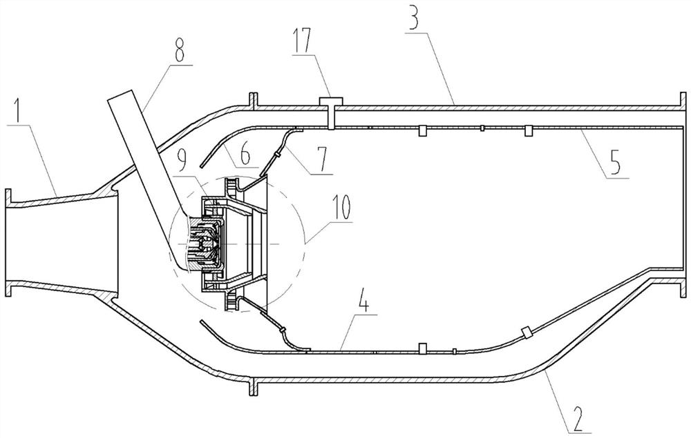
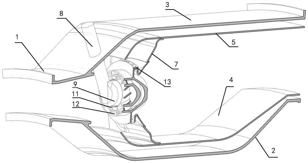
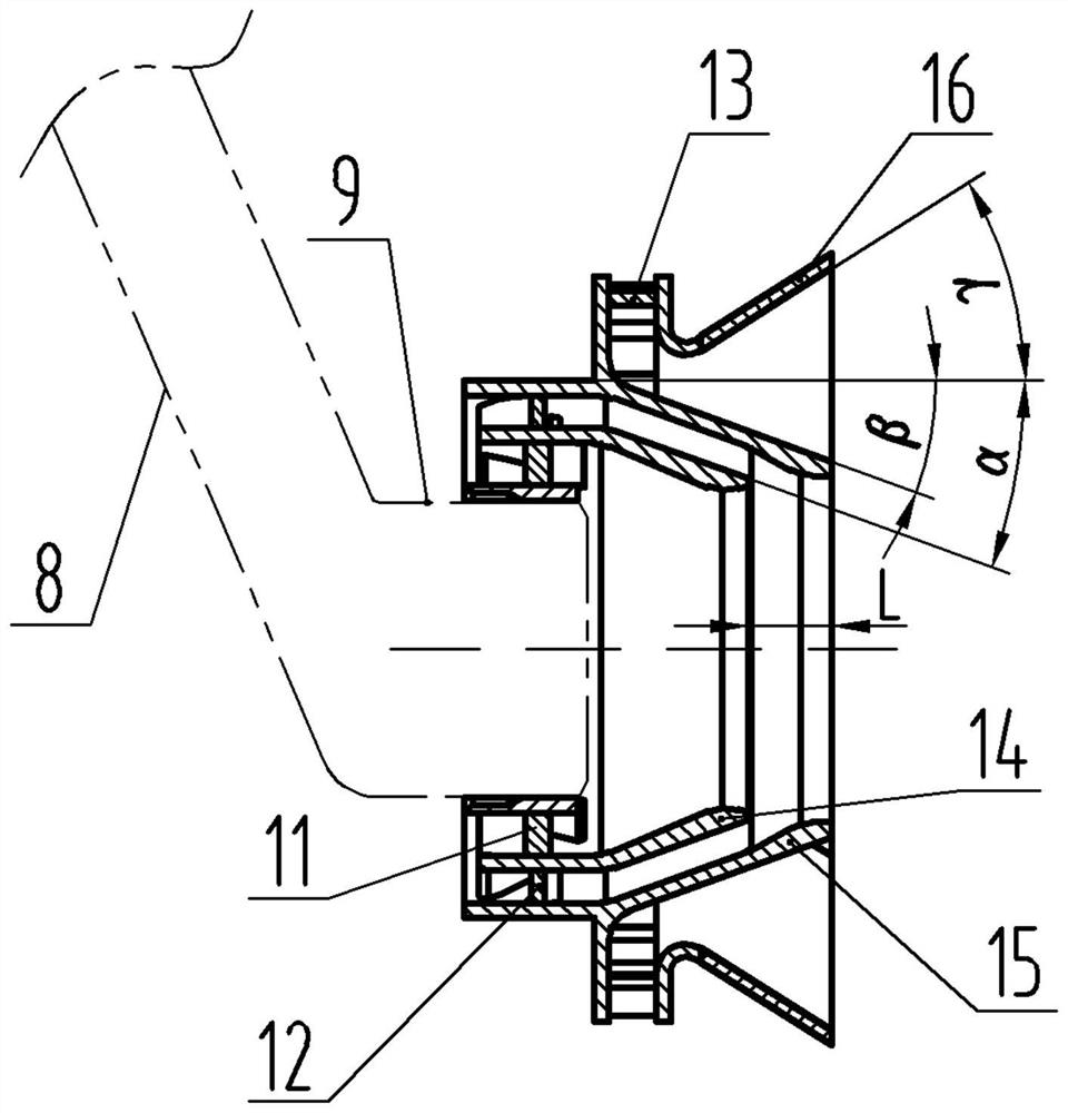
[0028] In the present di...


PUM

PropertyMeasurementUnit
Axial lengthaaaaaaaaaa

Abstract

The invention provides a double-necking-down combined spiral-flow type center grading high-temperature-rise combustion chamber which comprises a diffuser, an inner casing, an outer casing, a flame tube, a cap cover, a splash blocking disc, a fuel nozzle and a flame holder, the inner casing and the outer casing are connected with the tail end of the diffuser, and the fuel nozzle is used for conveying fuel oil to the flame tube; the flame holder is arranged on the outer side of the nozzle shell at the downstream end of the fuel nozzle in a sleeving manner and is coaxial with the nozzle shell; the flame holder comprises a first-stage swirler, a second-stage swirler and a third-stage swirler which are sequentially arranged in a sleeved mode, the outlet end face of the downstream of the first-stage swirler is connected with an inner necking opening, the outlet end face of the downstream of the second-stage swirler is connected with an outer necking opening, and the outlet end face of the downstream of the third-stage swirler is connected with a variable cross-section circular ring. The flame tube comprises a flame tube inner ring and a flame tube outer ring. By means of multi-path grading and echelon utilization of air, reliable ignition and combustion stability under the low working condition can be considered, and high-efficiency smoke-free combustion under the high working condition can also be considered.

Description

technical field [0001] The present disclosure relates to the technical field of aero-engines or gas turbines, in particular to a Diconvergent-nozzle Combined-swirl Internally-Staged HighTemperature Rise Combustor. Background technique [0002] In order to meet the high maneuverability requirements of modern fighter jets, it is required to develop high-performance aero-engines with high thrust-to-weight ratios. For this reason, aero-engines need to continuously pursue high cycle parameters. As the thrust-to-weight ratio target of aero-engines increases from 8 to 10 to 16 to 20, the total boost ratio target of the engine increases to more than 40, and the temperature target at the outlet of the combustion chamber is also increased from 1650K to 2150K, or even 2400K. In this way, the temperature rise of the combustion chamber will be raised from about 850K to 1150K, or even 1400K. At present, major aero-engine organizations are vigorously developing high-temperature rise combu...

Claims


Application Information

Patent Timeline
IPC IPC(8): F23R3/12F23R3/20F23R3/26F23R3/28F23R3/38F23R3/58
CPCF23R3/12F23R3/20F23R3/26F23R3/286F23R3/38F23R3/58Y02T50/60
Inventor 曾青华谢鹏福王步宇张健裴鑫岩周华
Owner TSINGHUA UNIV
Why Eureka
Try Eureka