Full-automatic inner cylinder machine

An inner cylinder machine, fully automatic technology, applied in the direction of offensive equipment, pyrotechnics, weapon types, etc., can solve the problems of slow production speed, low degree of mechanization, and low efficiency, and achieve the goal of increasing production speed, reducing costs, and shortening the production cycle Effect

Pending Publication Date: 2022-05-24
LIUYANG HENGBANG MACHINERY FACTORY
View PDF0 Cites 0 Cited by
  • Summary
  • Abstract
  • Description
  • Claims
  • Application Information

AI Technical Summary

Problems solved by technology

This method of winding the cylindrical cylinder with paper and making the closed end with mud or sealing agent has the problems of low degree of mechanization, slow production speed and low efficiency.

Method used


Image

  • Full-automatic inner cylinder machine
  • Full-automatic inner cylinder machine
  • Full-automatic inner cylinder machine

Examples


Embodiment 1

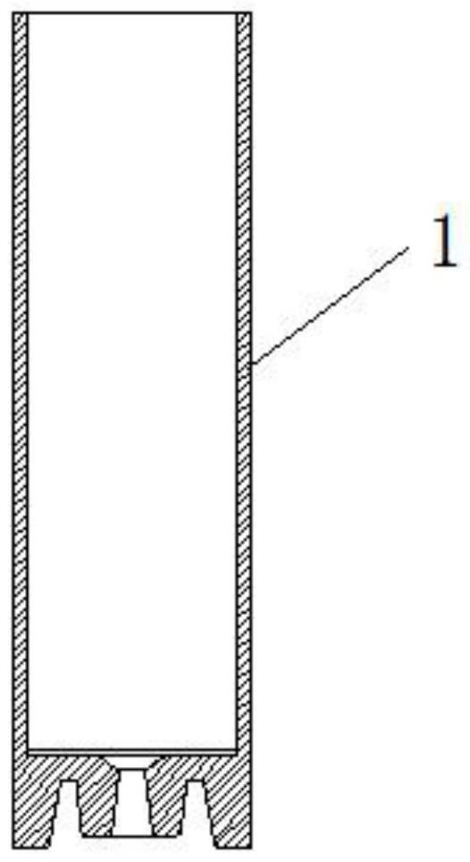
[0040] like figure 1 As shown, the inner cylinder 1 is in the prior art, the outer circumference of the inner cylinder 1 is cylindrical, the interior of the inner cylinder 1 is provided with an inner cavity that opens upward, and the bottom of the inner cylinder 1 is provided with a downward opening The center of the groove is provided with a downwardly protruding boss, and the center of the boss is provided with a lead hole. It should be noted that the inner cavity and bottom structure of the inner cylinder 1 can also adopt other shapes and structures, and can also be produced by using the fully automatic inner cylinder machine of the present invention.

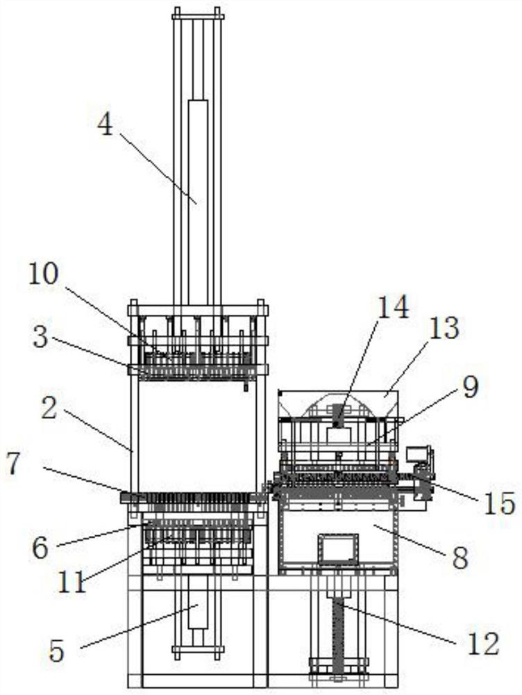
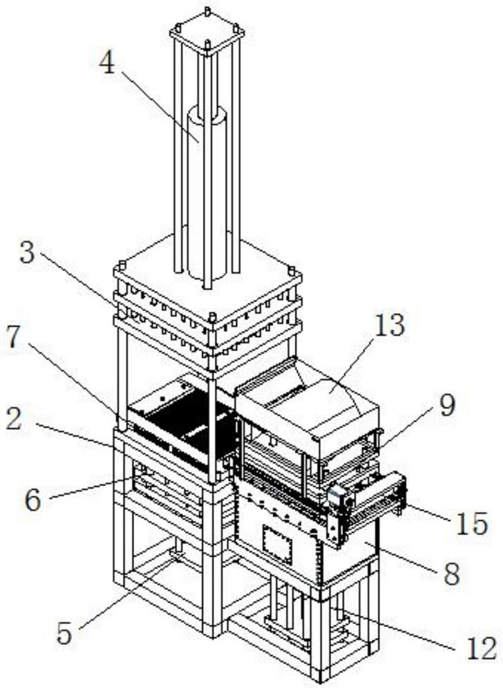
[0041] like Figure 2-12 As shown, a fully automatic inner cylinder machine includes a frame 2 , an upper pressing device 3 , an upper pushing mechanism 4 , a lower pushing mechanism 5 , a lower pressing device 6 , and a forming device 7 .

[0042] The rack 2 is composed of an upper rack 21 and a lower rack 22. The lower r...

Embodiment 2

[0071] like Figure 11 , Figure 12 , Figure 13 , Figure 14 As shown, a fully automatic inner cylinder machine includes an inner cylinder 1, a frame 2, an upper pressing device 3, an upper pushing mechanism 4, a lower pushing mechanism 5, a lower pressing device 6, and a forming device 7. The inner cylinder 1 is in the prior art, the outer circumference of the inner cylinder 1 is cylindrical, the interior of the inner cylinder 1 is provided with an inner cavity that opens upward, and the bottom of the inner cylinder 1 is provided with a groove that opens downward. The center of the groove is provided with a downwardly protruding boss, and the center of the boss is provided with a lead hole.

[0072]The frame 2 includes a base 221, a guide column 211, and a top plate 212. The base 221 is a rectangular or square base and is made of steel plate, cast steel or cast iron. The four corners of the base 221 are connected or welded by threaded holes. There are four vertically upw...


PUM


Abstract

The invention discloses a full-automatic inner barrel machine which comprises a rack, an upper pushing mechanism and an upper pressing device are installed on the upper portion of the rack, a lower pushing mechanism and a lower pressing device are installed on the lower portion of the rack, the upper pressing device comprises an upper pressing plate and an upper forming rod, and the lower pressing device comprises a lower forming rod and a lower pressing plate. A forming device is arranged between the upper pressing device and the lower pressing device, a plurality of forming through holes are formed in the forming device, the lower forming rods are matched with the forming through holes in shape and can slide up and down in the forming through holes, the upper forming rods are matched with the inner portion of the inner cylinder in shape, and the lower forming rods can slide up and down in the forming through holes. The upper forming rod can stretch into the forming through hole, the upper forming rod and the lower forming rod are matched with each other and pressed tightly, and an inner cylinder is formed in the forming through hole of the forming device. The problems that an existing inner cylinder is low in manufacturing speed, low in yield and high in cost are solved.

Description

technical field [0001] The invention relates to the technical field of firecrackers and fireworks equipment, in particular to a fully automatic inner cylinder machine for making inner cylinders of fireworks. Background technique [0002] Fireworks are generally composed of an outer cylinder, an inner cylinder and gunpowder. The shape of the inner cylinder is cylindrical, the interior of the inner cylinder is provided with an inner cavity that opens upward, and the bottom of the inner cylinder is provided with a groove that opens downward. The center of the groove is provided with a downwardly protruding boss, and the center of the boss is provided with a lead hole. The existing inner cylinder is generally made of paper and glue into a cylindrical cylinder by winding, and then the cylindrical cylinder is dried or dried, and then the closed end of the cylinder is made at the bottom of the cylinder with mud or sealing agent. . This method of winding paper to make a cylindrica...

Claims


Application Information

Patent Timeline
Patent Type & Authority Applications(China)
IPC IPC(8): F42B4/30
CPCF42B4/30
Inventor 王承意陶松林王天鹏戴和平
Owner LIUYANG HENGBANG MACHINERY FACTORY
Why Eureka
Try Eureka