Probe tool automatic design method, system and device and storage medium

An automatic design and probe technology, applied in the manufacture of computing systems, measuring devices, components of electrical measuring instruments, etc., can solve the problems of cumbersome and time-consuming operations, and achieve the effect of simplifying the operation logic and shortening the cycle.

Pending Publication Date: 2022-05-24
VAYO SHANGHAI TECH
View PDF0 Cites 0 Cited by
  • Summary
  • Abstract
  • Description
  • Claims
  • Application Information

AI Technical Summary

Problems solved by technology

[0004] However, when performing tooling interference analysis on test points, the existing technology needs to manually select the probe template for each test position, and the placement angle of the probe template needs to be adjusted manually, which is cumbersome and time-consuming.

Method used


Image

  • Probe tool automatic design method, system and device and storage medium
  • Probe tool automatic design method, system and device and storage medium
  • Probe tool automatic design method, system and device and storage medium

Examples


Embodiment 1

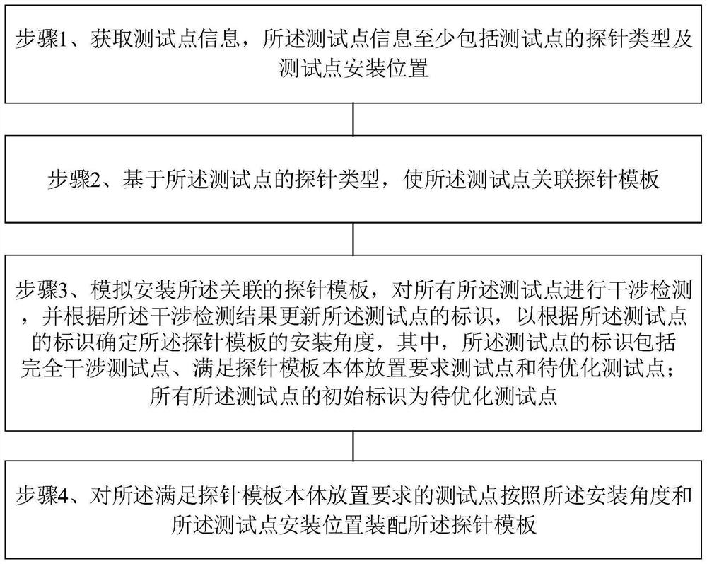
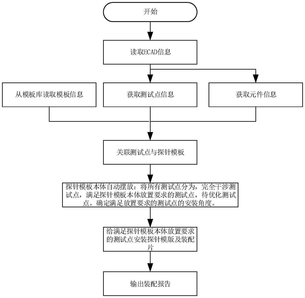
[0043] See figure 1 and figure 2 , figure 1 is a schematic flowchart of a method for automatic design of probe tooling provided by an embodiment of the present invention, figure 2 It is a schematic flowchart of another method for automatic design of probe tooling provided by the embodiment of the present invention. This embodiment provides a method for automatic design of probe tooling, and the method may include steps 1 to 6, wherein:

[0044] Step 1. Obtain test point information, where the test point information at least includes the probe type of the test point and the installation position of the test point.

[0045] (1) Obtain test point information according to the read ECAD data. The test point information includes:

[0046] a. Test point probe types: RF (radio frequency probe), BTB (connector test seat), TP (test point), CA (connector) and LED;

[0047] b. The attributes of the front and back of the test point: Group (when Group=0, the front side; when Group=1, ...

Embodiment 2

[0136] This embodiment further provides a specific method for automatic design of probe tooling on the basis of the above-mentioned embodiment, and the method includes:

[0137] 1. Obtain test point information.

[0138] The mounting surfaces of test points P0, P1, P2, P3, P4, P5, P6, P7, and P8 are BOTTOM surfaces, so the attributes of the front and back of the test points are: Group=1;

[0139] The probe types of test points P0, P1, P2, P3, P5, P6, and P7 are all RF, the body flag type is 1, and the rotatable type; the test point names (bit numbers) are: P0: RN800, P1: RN801, P2: RN802, P3: RN803, P5: RN805, P6: RN806, P7: RN807;

[0140] The installation positions of the test points are: ((P0(10,30), P1(10,27), P2(12,25), P3(18,20), P5(28,15), P6(43,20) ,P7(50,20));

[0141] The probe type of the test point P4 is BTB; the body mark bit type is 2, which cannot be rotated; the test point installation position is P4 (25,25), and the test point name (bit number) is Q1205;

...

Embodiment 3

[0180] See Figure 14 , Figure 14 It is a schematic diagram of a system for automatic design of probe tooling provided by an embodiment of the present invention. The system for the automatic design of the probe tooling includes:

[0181] an acquisition module for acquiring test point information, where the test point information at least includes the probe type of the test point and the installation position of the test point;

[0182] an association module, configured to associate the test point with a probe template based on the probe type of the test point;

[0183] The installation angle determination module simulates the installation of the associated probe template for performing interference detection on all the test points, and updates the identification of the test point according to the interference detection result, so as to determine the probe template according to the identification of the test point installation angle, wherein, the identification of the test ...


PUM


Abstract

The invention discloses a probe tool automatic design method, system and device and a storage medium, and the method comprises the steps: 1, obtaining the information of a test point, the information of the test point comprising the probe type of the test point and the installation position of the test point; step 2, based on the probe type of the test point, enabling the test point to be associated with a probe template; 3, simulating the installation of the associated probe template, carrying out interference detection on all the test points, updating the identification of the test points according to an interference detection result, and determining the installation angle of the probe template according to the identification of the test points; and step 4, assembling the probe template for the test points meeting the placement requirements of the probe template body according to the installation angles and the installation positions of the test points. According to the method, the probe template is assembled for the test points, interference inspection is carried out, the test points are divided into complete interference test points, test points meeting placement requirements and test points to be optimized, and finally the assembly report is output, so that automatic design of the probe tool is realized.

Description

technical field [0001] The invention belongs to the technical field of electronic manufacturing, and in particular relates to a method, system, equipment and storage medium for automatic design of probe tooling. Background technique [0002] In the production process of PCB (Printed Circuit Board, printed circuit board), the probe test plays an extremely important role in the field of detection of tooling interference at the test point. In the process of probe test, the pre-set coordinate position program is generally used. The mobile test probes are in contact with it, and each test probe performs open-short circuit or signal test on the PCB assembly components according to the test procedure. [0003] The test program of the online tester is generally automatically generated. The method is to read the position of the test point by ECAD (Electronic Computer Aided Design), and then combine the test point data and component data to generate the test program. [0004] However...

Claims


Application Information

Patent Timeline
Patent Type & Authority Applications(China)
IPC IPC(8): G01R1/067G01R31/26
CPCG01R1/067G01R31/26Y02P90/30
Inventor 邵栋栋刘继硕刘丰收
Owner VAYO SHANGHAI TECH
Why Eureka
Try Eureka