Trench isolation structure forming method and image sensor forming method

A trench isolation and trench technology, which is applied in semiconductor devices, electrical solid state devices, semiconductor/solid state device manufacturing, etc., can solve problems such as height difference, affecting device performance and reliability in logic areas, etc., to improve device performance and reliability effect

Inactive Publication Date: 2022-05-24
NEXCHIP SEMICON CO LTD
View PDF9 Cites 1 Cited by
  • Summary
  • Abstract
  • Description
  • Claims
  • Application Information

AI Technical Summary

Problems solved by technology

[0004] The object of the present invention is to provide a method for forming a trench isolation structure to solve the problem of chemical mechanical problems due to the difference in height between the logic region and the pixel region due to the dry etching of the logic region twice during the formation of the image sensor. After grinding, the oxide layer still remains on the logic area, which affects the device performance and reliability of the logic area.

Method used


Image

  • Trench isolation structure forming method and image sensor forming method
  • Trench isolation structure forming method and image sensor forming method
  • Trench isolation structure forming method and image sensor forming method

Examples


Embodiment Construction

[0040] The method for forming a trench isolation structure and a method for forming an image sensor proposed by the present invention will be further described in detail below with reference to the accompanying drawings and specific embodiments. The advantages and features of the present invention will become more apparent from the following description. It should be noted that the accompanying drawings are all in a very simplified form and in inaccurate scales, and are only used to facilitate and clearly assist the purpose of explaining the embodiments of the present invention.

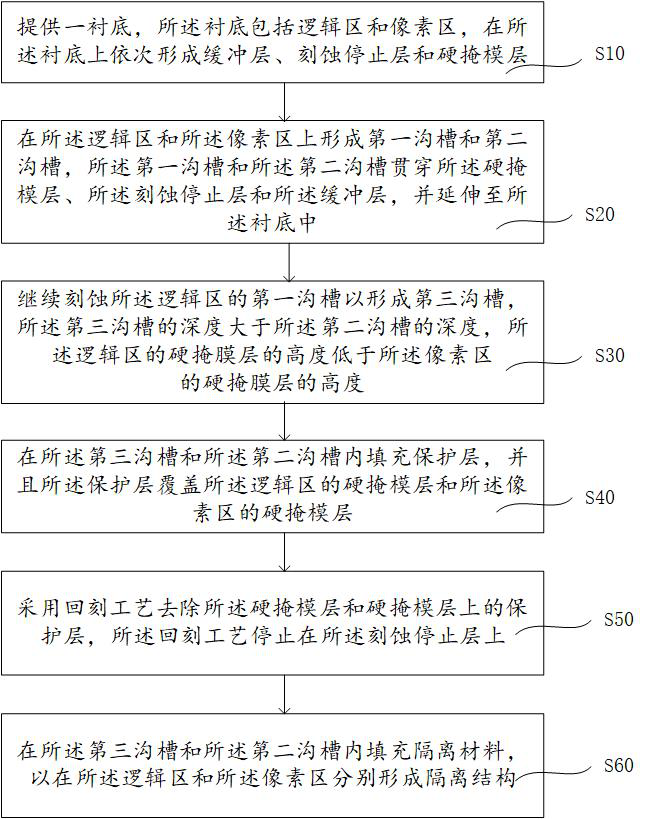
[0041] For details, please refer to figure 1 , which is a flowchart of a method for forming a trench isolation structure according to an embodiment of the present invention. like figure 1 As shown, this embodiment provides a method for forming a trench isolation structure, including:

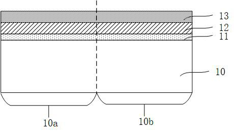
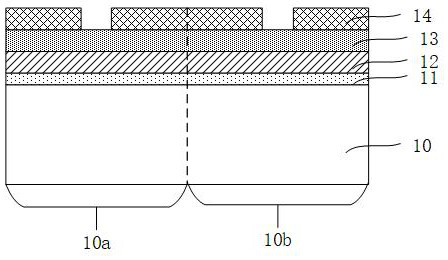
[0042] Step S10, a substrate is provided, the substrate includes a logic region and a pixel region, and a buffer ...


PUM

PropertyMeasurementUnit
thicknessaaaaaaaaaa
thicknessaaaaaaaaaa

Abstract

The invention provides a forming method of a trench isolation structure and a forming method of an image sensor, and the method comprises the steps: providing a substrate which comprises a logic region and a pixel region, and sequentially forming a buffer layer, an etching stop layer and a hard mask layer on the substrate; forming a first groove and a second groove with the same depth on the logic region and the pixel region; the second groove of the pixel area is covered, the first groove of the logic area is continuously etched to form a third groove, the third groove is the extension of the first groove, and the depth of the third groove is larger than that of the second groove; filling a protective layer in the third groove and the first groove, wherein the protective layer covers the hard mask layer; and removing the hard mask layer and the protective layer on the hard mask layer by adopting an etch-back process, wherein the etch-back process is stopped on the etching stop layer.

Description

technical field [0001] The present invention relates to the field of semiconductor technology, and in particular, to a method for forming a trench isolation structure and a method for forming an image sensor. Background technique [0002] An image sensor usually includes a logic area and a pixel area. In an existing STI (shallow trench isolation) process, different STI formation methods are used in the logic area and the pixel area to avoid dry etching. etch) residual plasma has an impact on the photoelectric conversion performance of the pixel area. Specifically, firstly, through the first dry etching process, a trench having a first depth is obtained by etching. Further, a second dry etching process is continued in the logic region, and a trench of a second depth (also called an STI extension trench or a deep trench) is obtained by etching the trench of the first depth. The second depth is greater than the first depth. A trench isolation structure is formed in the trenc...

Claims


Application Information

Patent Timeline
Patent Type & Authority Applications(China)
IPC IPC(8): H01L27/146H01L21/762
CPCH01L27/1463H01L27/14632H01L27/14687H01L21/76224
Inventor 陶磊林子荏林士程
Owner NEXCHIP SEMICON CO LTD
Why Eureka
Try Eureka