Manufacturing method of grid electrode

A manufacturing method and gate technology, applied in the field of gate manufacturing, can solve problems such as cumbersome process flow, and achieve the effects of solving different gate heights, simplifying the manufacturing process, and improving yield

Inactive Publication Date: 2019-11-19
SHANGHAI HUALI INTEGRATED CIRCUTE MFG CO LTD
View PDF5 Cites 1 Cited by
  • Summary
  • Abstract
  • Description
  • Claims
  • Application Information

AI Technical Summary

Problems solved by technology

[0007] The present application provides a gate manufacturing method, which can solve the problem that

Method used


Image

  • Manufacturing method of grid electrode
  • Manufacturing method of grid electrode
  • Manufacturing method of grid electrode

Examples


Embodiment Construction

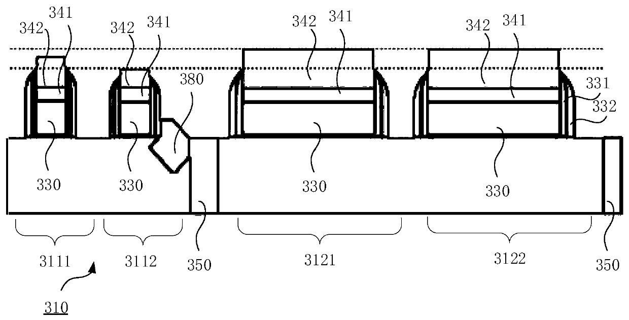
[0051] The technical solutions in this application will be clearly and completely described below in conjunction with the accompanying drawings. Apparently, the described embodiments are some of the embodiments of this application, not all of them. Based on the embodiments in this application, all other embodiments obtained by persons of ordinary skill in the art without making creative efforts belong to the scope of protection of this application.

[0052] In the description of this application, it should be noted that the terms "center", "upper", "lower", "left", "right", "vertical", "horizontal", "inner", "outer" etc. The indicated orientation or positional relationship is based on the orientation or positional relationship shown in the drawings, and is only for the convenience of describing the present application and simplifying the description, rather than indicating or implying that the referred device or element must have a specific orientation, use a specific orientati...


PUM


Abstract

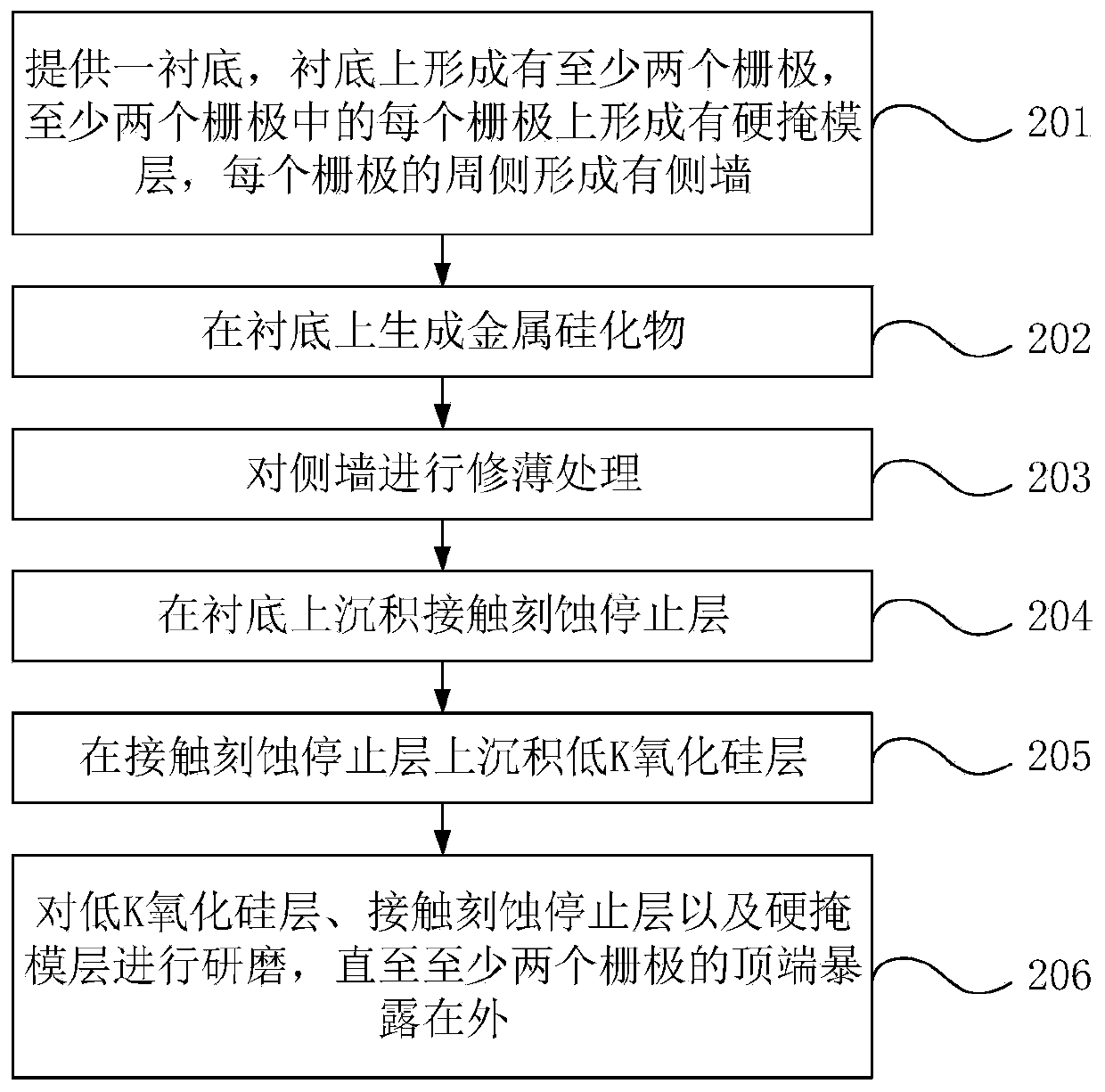
The invention discloses a manufacturing method of a grid electrode. The method comprises the following steps of providing a substrate, forming at least two grid electrodes on the substrate, forming ahard mask layer on each of the at least two grid electrodes, and forming a sidewall on a peripheral side of each grid electrode; generating metal silicide on the substrate; thinning the sidewall; depositing a contact etching stop layer on the substrate; depositing a low-K silicon oxide layer on the contact etching stop layer; grinding the low-K silicon oxide layer, the contact etching stop layer,and the hard mask layer till that top ends of the at least two grid electrodes are exposed. After the metal silicide is generated, a complicated photoresist etchback step is replaced by grinding so that a manufacturing process is simplified. At the same time, because the photoresist etchback step is not required, a problem of different grid electrode heights caused by the photoresist etchback stepis solved, and a yield of a manufacturing process is improved.

Description

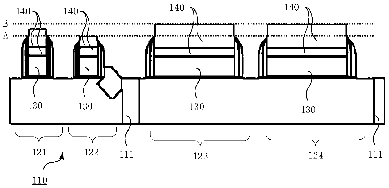
technical field [0001] The present application relates to the technical field of semiconductor manufacturing, and in particular to a method for manufacturing a gate. Background technique [0002] In the related art, semiconductor devices applied to logic chips include n-type field effect transistors (n FieldEffect Transistor, nFET) and pFETs. In the manufacturing process of pFET or nFET, after metal silicide is formed on the substrate of pFET or nFET, photoresist etch back (Photo Resistor Etch Back, PREB) will be carried out. By covering the gate with photoresist, the The hard mask layer is etched back. [0003] figure 1 A schematic diagram showing the gate formed by the manufacturing method provided by the related art, refer to figure 1 , a shallow trench isolation (Shallow Trench Isolation, STI) structure 111 is formed on the substrate 110 . [0004] The shallow trench isolation structure 111 isolates the active area on the substrate 110, the active area includes the a...

Claims


Application Information

Patent Timeline
IPC IPC(8): H01L21/8238H01L21/28
CPCH01L21/28017H01L21/823828H01L21/82385
Inventor 张书明薛培堃陈明志
Owner SHANGHAI HUALI INTEGRATED CIRCUTE MFG CO LTD
Why Eureka
Try Eureka