
Direct current screen convenient for dust cleaning

A DC screen and dust technology, applied in the field of DC screen, can solve the problems of heat accumulation, easy adhesion of dust, unfavorable use, etc., to achieve the effect of ensuring ventilation performance, avoiding adhesion dust, and ensuring cleanliness

Inactive Publication Date: 2022-05-24
南通爱迪电气有限公司
View PDF0 Cites 0 Cited by
  • Summary
  • Abstract
  • Description
  • Claims
  • Application Information

AI Technical Summary

Problems solved by technology

[0003] When the DC screen is working, the electrical components will generate a lot of heat. Now the ventilation components are designed to discharge the heat. However, the angle of the air blowing into the existing ventilation components is fixed, and the local heat dissipation effect is better. Some parts will have heat accumulation. If the heat in the heat accumulation place is not discharged in time, it will cause damage to electrical components, which is not conducive to practical use. At the same time, the surface of the dust filter component of the ventilation component is easy to stick to dust, and the ventilation performance of the dust filter component is poor.

Method used


Image

  • Direct current screen convenient for dust cleaning
  • Direct current screen convenient for dust cleaning
  • Direct current screen convenient for dust cleaning

Examples


Embodiment 1

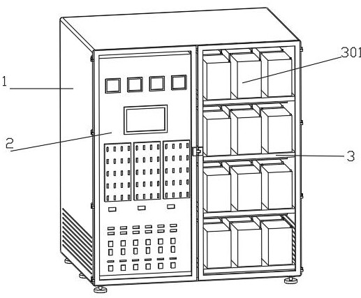
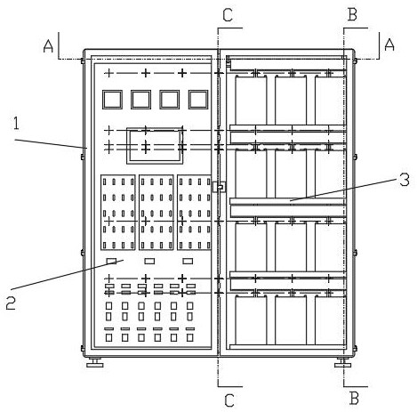
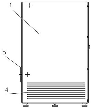
[0043] like Figure 1-13 As shown in the figure, the DC screen is easy to clean the dust, including the DC screen box 1, the DC screen control unit 2 and the battery support plate 3. The lower ends of the two side walls of the DC screen box 1 are evenly opened with air outlets 4, and the DC screen control unit 2 and the battery support plate 3. The battery support plates 3 are respectively arranged on both sides inside the DC panel box 1. The top of the battery support plate 3 is evenly connected with the batteries 301, and the batteries 301 are arranged in a 3*3 array on the top of the battery support plate 3. The DC panel box 1 The rear side wall is provided with an air intake assembly, the air intake assembly is connected with a quick connection assembly, the quick connection assembly is movably connected with a filter screen 7, and the air intake assembly is connected with a dust cleaning assembly, which is movably connected with the filter screen 7, and the air intake The...

Embodiment 2

[0046] On the basis of Example 1, see image 3 , 4 As shown in and 8, the air intake assembly includes an air intake hood 5, an air intake fan 18 and an air intake pipe 19, and an air intake hood 5 is installed in the mounting hole of the rear side wall of the DC screen box 1, and the air outlet end of the air intake hood 5 is connected to the intake air hood 5. The input end of the air fan 18 is fixedly connected, the air intake fan 18 is installed on the inner wall of the DC panel box 1, and the output end of the air intake fan 18 is fixedly connected with an air intake pipe 19.

[0047] The filter screen 7 filters the air, and the air intake fan 18 of the air intake assembly draws clean air into the air intake pipe 19 through the air intake cover 5 to facilitate driving the clean air into the DC screen box 1 .

Embodiment 3

[0049] On the basis of Example 2, see Figure 9 and 12 As shown, the quick-connect assembly includes a limit rod 32 and a fixed outer cover 33, the outer end side wall of the air intake cover 5 is fixed with the limit rod 32 at equal intervals along the circumferential direction, and the outer end of the air intake cover 5 is threadedly connected with a fixed outer cover 33. The net 7 is inserted into the limit rod 32 through the opening hole. When the fixed outer cover 33 and the air intake cover 5 are connected, the fixed outer cover 33 presses the filter screen 7 against the outer end of the air intake cover 5 .

[0050] The filter screen 7 is plugged with the limit rod 32 of the quick-connect assembly, which is convenient for the filter screen 7 to be installed on the limit rod 32. At the same time, the fixed outer cover 33 is threadedly connected with the air intake cover 5, which is convenient for the fixed outer cover 33 to be installed on the air intake cover 5. On th...


PUM


Abstract

The invention discloses a direct-current screen convenient for dust cleaning, and relates to the technical field of direct-current screens, the direct-current screen comprises a direct-current screen box body, a direct-current screen control unit and a storage battery supporting plate, the direct-current screen control unit and the storage battery supporting plate are respectively arranged at two sides in the direct-current screen box body, and the top of the storage battery supporting plate is uniformly connected with storage batteries; an air inlet assembly is arranged on the rear side wall of the direct current screen box body and connected with a quick connection assembly, the quick connection assembly is movably connected with a filter screen, the air inlet assembly is connected with a dust cleaning assembly, the dust cleaning assembly is movably connected with the filter screen, and a reciprocating type air injection assembly is arranged at the air outlet end of the air inlet assembly. The reciprocating air injection assembly is arranged on the rear side of the direct-current screen control unit and the storage battery supporting plate. By means of the mode, heat generated by electrical elements can be discharged in time, the phenomenon of heat accumulation is avoided, the electrical elements are protected, actual use is facilitated, meanwhile, dust is prevented from being bonded to the surface of the filter screen, and the ventilation performance of the filter screen is guaranteed.

Description

technical field [0001] The invention relates to the technical field of DC screens, in particular to a DC screen that is convenient for cleaning dust. Background technique [0002] The common name of the DC screen is the intelligent maintenance-free DC power screen, which is the basis for the control and protection of the contemporary power system. Composed of monitoring module unit and insulation monitoring unit, it is mainly used in small and medium-sized power plants, hydropower stations, various substations, and other users of DC equipment (such as petrochemicals, mines, railways, etc.) in the power system. Instruments, meters, relay protection and fault lighting in the secondary circuit. [0003] When the DC screen is working, the electrical components will generate a lot of heat. Now, the ventilation components are designed to discharge the heat. However, the existing ventilation components have a fixed angle of air blowing, and the local heat dissipation effect is bet...

Claims


Application Information

Patent Timeline
Patent Type & Authority Applications(China)
IPC IPC(8): H02J7/00H02J11/00H02B1/28H02B1/46H02B1/48H02B1/56B01D46/681B01D46/88B01D46/10H05K7/20
CPCH02J7/0013H02J7/0042H02J7/0029H02J7/00309H02J7/0063H02J11/00H02B1/46H02B1/48H02B1/565H02B1/28B01D46/10H05K7/20181H05K7/20145H05K7/20136H05K7/20909Y02A50/2351
Inventor 陈顺国顾春健
Owner 南通爱迪电气有限公司
Learn More