Pulping device for plant fiber molded product and processing method thereof

A technology of molded products and plant fibers, which is applied in chemical instruments and methods, transportation and packaging, recycling technology, etc., can solve the problems of long pulping time and high cost of manual assistance, and achieve the purpose of reducing the occupation of the site and eliminating Complicated, efficiency-enhancing effects

Pending Publication Date: 2022-05-27
安徽瑞可环保科技有限公司
5 Cites 2 Cited by

AI-Extracted Technical Summary

Problems solved by technology

[0007] The purpose of the present invention is to provide a pulping device for plant fiber molded products and its processing method, to solve the above-mentioned bac...

Method used

According to Fig. 1-4 and shown in Fig. 6, mixing and stirring mechanism comprises a plurality of metal rods 301, and the top of a plurality of metal rods 301 is all fixedly inserted in the bottom of protective shell 1, and the outer wall of a plurality of metal rods 301 A connecting ring B302 is provided between the fixed sleeves, and a servo motor B303 is fixedly inserted into the inner wall of the connecting ring B302. The output end of the servo motor B303 is fixedly installed with a transmission rod B304, and the bottom of the inner wall of the protective shell 1 is fixedly installed with an inner tank 307. The top of the transmission rod B304 runs through the bottom of the protective shell 1 and is placed inside the inner tank 307. The outer wall of the transmission rod B304 is fixedly sleeved with a connecting plate 305, and the top of the connecting plate 305 is welded with a stirring rod 306. The protective shell 1 A plurality of conductive rods 308 are fixedly installed at the bottom of the inner wall, and a group of heating rods 309 are fixedly connected to one side of the outer wall of each of the plurality of conductive rods 308, and one end of the outer wall of each of the plurality of groups of heating rods 309 runs through the inner container 307. The outer wall is located inside the inner tank 307. By setting the mixing and stirring mechanism, the powdery material can be quickly stirred into the reaction liquid, so that the distribution of the material in the liquid is relatively uniform, and finally the quality of the later slurry is provided.
According to Fig. 1-4 and shown in Fig. 7-8, information control mechanism comprises grafting plate 401, and the outer wall of grafting plate 401 is fixedly installed on the outer wall side of protective casing 1, and the top of grafting plate 401 is fixedly installed with control A device 402, a rectangular groove 403 is provided on one side of the outer wall of the protective shell 1, and two information connectors 404 are arranged inside the rectangular groove 403, and a reproduced main board 405 is fixedly installed inside the controller 402, and the outer wall of the reproduced main board 405 is fixedly connected with Two contact bases 406, the inside of the two contact bases 406 are respectively provided with a central control module 407 and a command issuing module 408, the central control module 407 and the command issuing module 408 are connected in series through a wire, the two information connectors 404 The interior is fixedly connected with information...

Abstract

The invention discloses a pulping device for plant fiber molded products and a processing method thereof.The pulping device is characterized in that a material crushing mechanism and a mixing and stirring mechanism are fixedly mounted in a protective shell, an information control mechanism is fixedly mounted on one side of the outer wall of the protective shell, and the material crushing mechanism comprises a top cover; the top cover is movably arranged at the top of the protective shell, a feeding hole is formed in the center of the top of the top cover, a plurality of components are integrated to achieve the autonomous linkage capacity, part of control elements are added, all the components are started in order in the working process of the device, the complexity of manual operation is eliminated, and the working efficiency is improved. The whole size of the device is reduced, occupied space is reduced, the problem that due to the fact that an existing device is single in structure, multiple devices need to be used for operation in each pulping process, and materials need to be manually carried in each stage is effectively solved, the pulping efficiency of the device is improved, and meanwhile output of labor cost is reduced.

Application Domain

Transportation and packagingPaper recycling +2

Technology Topic

Process engineeringMultiple device +5

Image

  • Pulping device for plant fiber molded product and processing method thereof
  • Pulping device for plant fiber molded product and processing method thereof
  • Pulping device for plant fiber molded product and processing method thereof

Examples

  • Experimental program(1)

Example Embodiment

[0034]The technical solutions in the embodiments of the present invention will be clearly and completely described below with reference to the accompanying drawings in the embodiments of the present invention. Obviously, the described implementation regulations are only a part of the embodiments of the present invention, not all of the embodiments. Based on the embodiments of the present invention, all other embodiments obtained by those of ordinary skill in the art without creative efforts shall fall within the protection scope of the present invention.
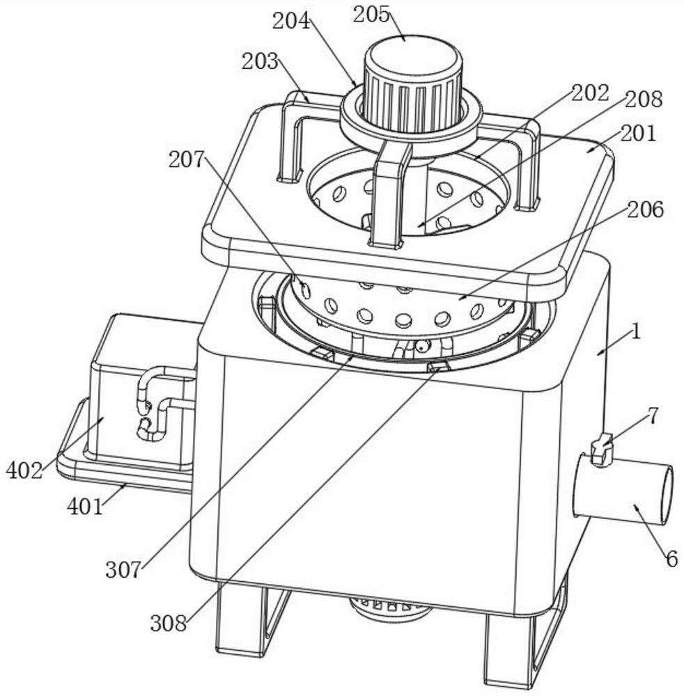
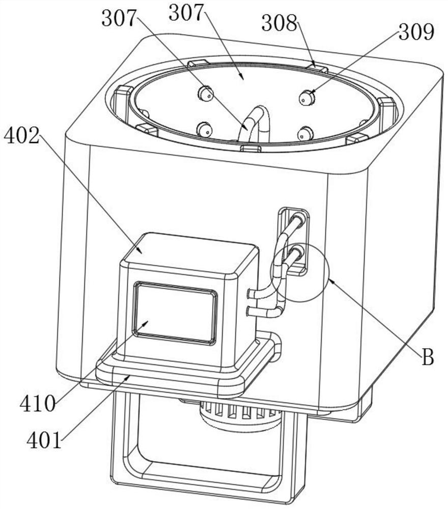
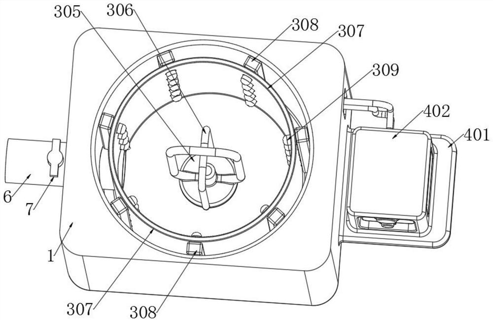
[0035] see Figure 1-8 As shown, the present invention provides a technical solution: a pulping device for plant fiber molded products, comprising: a material crushing mechanism and a mixing and stirring mechanism are respectively fixedly installed in the interior of the protective casing 1, and the outer wall of the protective casing 1 is fixed on one side. Installed with an information control mechanism, the device achieves the ability of autonomous linkage by integrating multiple components, adding some control elements, so that each component can be started in an orderly manner during the work process of the device, eliminating the tediousness of manual operation, Reduce the overall volume of the device, reduce the occupation of the site, effectively solve the problem that the existing device has a single structure, so that each pulping needs to be operated with multiple equipment, resulting in the need to manually transport materials at each stage. The efficiency of the pulp, while also reducing the output of labor costs.
[0036] according to figure 1 and Figure 5 As shown, the material crushing mechanism includes a top cover 201, the top cover 201 is movably arranged on the top of the protective casing 1, a feeding hole 202 is opened at the top center of the top cover 201, and a plurality of metal L-shaped frames are welded on the top of the top cover 201 203, a connecting ring A204 is fixedly installed between the tops of the plurality of metal L-shaped frames 203, the inner surface wall of the connecting ring A204 is fixedly inserted with a servo motor A205, and the bottom of the servo motor A205 is fixedly installed with a limit sleeve, and the top cover 201 A grinding cylinder 206 is fixedly installed at the bottom of the grinding cylinder 206, and a plurality of discharge holes 207 are opened on the outer wall of the grinding cylinder 206. The diameters of each of the plurality of discharge holes 207 are equal, and the output end of the servo motor A205 is fixedly installed with a transmission rod. A208, the outer wall of the transmission rod A208 is movably placed inside the limit sleeve, the outer wall of the transmission rod A208 is fixedly sleeved with a transfer plate 209, and the interior of the transfer plate 209 is fixedly inserted with a plurality of alloy pin knives 210, setting materials The crushing mechanism directly connects multiple parts of the mechanism to the whole device, and adopts the operation mode of mechanical transmission to quickly make the material into shredded powder, and quickly enter the device to mix with the reaction liquid, effectively preventing the use of independent equipment for crushing. After the material is transported, a certain amount of loss is caused due to the influence of the airflow during the handling process, and the time for material transportation is also shortened.
[0037] according to Figure 1-4 and Image 6 As shown, the mixing and stirring mechanism includes a plurality of metal rods 301, the tops of the plurality of metal rods 301 are fixedly inserted in the bottom of the protective casing 1, and a connecting ring B302 is fixedly sleeved between the outer walls of the plurality of metal rods 301 to connect The inner surface wall of the ring B302 is fixedly inserted with a servo motor B303, the output end of the servo motor B303 is fixedly installed with a transmission rod B304, the bottom of the inner wall of the protective casing 1 is fixedly installed with an inner tank 307, and the top of the transmission rod B304 penetrates the protective casing 1. The bottom is placed inside the inner pot 307, the outer wall of the transmission rod B304 is fixedly sleeved with a connecting plate 305, the top of the connecting plate 305 is welded with a stirring rod 306, and the bottom of the inner wall of the protective shell 1 is fixedly installed with a plurality of conductive rods 308 , one side of the outer wall of each of the plurality of conductive rods 308 is fixedly connected with a group of heating rods 309, and one end of the outer wall of each of the plurality of groups of heating rods 309 penetrates the outer wall of the inner pot 307 and is located inside the inner pot 307, By setting the mixing and stirring mechanism, the powdery material can be quickly stirred into the reaction liquid, so that the distribution of the material in the liquid is relatively uniform, and finally the quality of the slurry in the later stage is provided.
[0038] according to Figure 1-4 and Figure 7-8 As shown, the information control mechanism includes a grafting plate 401, the outer wall of the grafting plate 401 is fixedly installed on one side of the outer wall of the protective casing 1, the top of the grafting plate 401 is fixedly installed with a controller 402, and one side of the outer wall of the protective casing 1 is provided with a rectangular Slot 403, the interior of the rectangular slot 403 is provided with two information connectors 404, the inside of the controller 402 is fixedly installed with a reloading mainboard 405, and the outer wall of the reloading mainboard 405 is fixedly connected with two contact bases 406, two contact bases 406 There are a central control module 407 and a command issuing module 408 in the inner part, the central control module 407 and the command issuing module 408 are connected in series through a wire, and the inside of the two information connectors 404 are fixedly connected with an information line 409. The two information lines The input terminals of 409 are all fixedly connected to the terminals of the controller 402. By setting up an information control mechanism, a plurality of operation instructions input into the central control module 407 are used and analyzed by the central control module 407. Multiple components are effectively controlled, so that the workmanship of each component can maximize energy utilization, prevent components from doing useless work, and effectively reduce energy loss.
[0039] according to Figure 1-4 As shown, the bottom of the protective shell 1 is fixedly installed with two brackets 5 through two sets of screws, and the outer wall of the protective shell 1 is provided with a slurry outlet pipe 6, and the feeding end of the slurry outlet pipe 6 penetrates the protective shell 1 and the inner tank 307 respectively. The outer wall is communicated with the interior of the inner liner 307. The inside of the slurry outlet pipe 6 is provided with a one-way valve 7. By setting the one-way valve 7 in the slurry outlet pipe 6, the phenomenon of leakage when the liquid is mixed is prevented.
[0040] The effect achieved by the whole mechanism is: first, move the device to the designated working area, make the bracket 5 at the bottom of the protective shell 1 fully contact the ground, remove the top cover 201 to make it detach from the top of the protective shell 1, and make the required response. The liquid is poured into the inner tank 307, and the top cover 201 is covered on the protective casing 1 again, the required materials are placed into the grinding cylinder 206, and the servo motor A205 in the connecting ring A204 is activated to act on the transmission rod A208 to drive the reprint. The alloy pin knife 210 on the disc 209 makes it continuously cut and grind the material, and finally form a powder, and under the influence of the air flow, it enters into the inner tank 307 from the discharge hole 207 to contact with the reaction liquid, and the connecting ring is activated. The servo motor B303 in the B302 acts on the transmission rod B304 to rotate the stirring rod 306 on the connecting plate 305 to stir the mixed liquid. Before the operation of the whole device, it first transmits the transmission to the central control module 407 in the main board 405. The operation instruction is analyzed by the central control module 407 to control the working time of the device, and is transmitted to the command issuing module 408 through the wire to enter the release of the command information, and then the connection relationship between the information wire 409 and the information connector 404 , import the information into the protective casing 1, and control the components. When the slurry preparation is completed, open the one-way valve 7, so that the slurry can flow out from the slurry outlet pipe 6.
[0041] The present invention also provides a processing method of a pulping device for plant fiber molded products, comprising the following steps:
[0042] Step 1: First, put the required material into the grinding cylinder 206 through the feeding hole 202, pour the mixed liquid into the inner tank 307, put the top cover 201 on the top of the protective shell 1, and start The servo motor A205 drives the alloy pin knife 210 on the transfer plate 209 to rotate at a high speed in the grinding cylinder 206, and pulverizes the material. 307 Neutralize the liquid for mixing.
[0043] Step 2: further start the servo motor B303 on the connecting ring B302, make the stirring rod 306 on the connecting plate 305 rotate at a high speed inside the inner tank 307, and accelerate the mixing of the liquid and the material powder, so that the slurry obtained later has its internal material. distribution is more even.
[0044] Step 3: The operation mode, interval time and sequence of each component of the device are entered into the central control module 407 before the device is in operation. When the device is in operation, the central control module 407 transmits the signal to the command issuing module 408 according to the code instruction. , and then the heating rods 309 are respectively introduced into a plurality of components in the protective casing 1 .
[0045] The entire processing method of the pulping device for plant fiber molded products is roughly the same as the above-mentioned pulping device for plant fiber molded products. The main difference is that when the liquid and material are stirred in the stirring rod 306 At the same time, the current entering the protective shell 1 is quickly introduced into the conductive rod 308 at the bottom of the inner wall of the protective shell 1, and is introduced into each heating rod 309 respectively, and the current enters the heating rod 309 for autonomous heat release, and When reaching the designated temperature quickly, each heating rod 309 is evenly distributed in the inner liner 307 and fully contacted with the mixed liquid, which effectively accelerates the molecular activity of the material and further improves the pulping rate.
[0046] Although the present invention has been described in detail with reference to the foregoing embodiments, for those skilled in the art, it is still possible to modify the technical solutions described in the foregoing embodiments, or to perform equivalent replacements for some of the technical features. Any modification, equivalent replacement, improvement, etc. made within the spirit and principle of the present invention shall be included within the protection scope of the present invention.

PUM

no PUM

Description & Claims & Application Information

We can also present the details of the Description, Claims and Application information to help users get a comprehensive understanding of the technical details of the patent, such as background art, summary of invention, brief description of drawings, description of embodiments, and other original content. On the other hand, users can also determine the specific scope of protection of the technology through the list of claims; as well as understand the changes in the life cycle of the technology with the presentation of the patent timeline. Login to view more.

Similar technology patents

Video coding apparatus

ActiveUS20070217507A1reduce volumereduce image quality
Owner:FUJITSU LTD

Slave core software cache sharing method for many-core processor

PendingCN112463711AEliminate cumbersomenessEnsure data consistency
Owner:BEIHANG UNIV

Classification and recommendation of technical efficacy words

  • Eliminate cumbersomeness
  • reduce volume

Slave core software cache sharing method for many-core processor

PendingCN112463711AEliminate cumbersomenessEnsure data consistency
Owner:BEIHANG UNIV

Implant release mechanism

ActiveUS20080140178A1reduce volumereduce outer diameter
Owner:COOK MEDICAL TECH LLC

Speed reduction box for turbine fracturing

Owner:YANTAI JEREH PETROLEUM EQUIP & TECH

Miniature and Multi-Band RF Coil Design

ActiveUS20100090824A1reduce volumelong wavelength
Owner:HONG KONG APPLIED SCI & TECH RES INST

Automatic washing and dewatering combined device of rotary type mop

InactiveCN102370447Areduce volumeSimple structure
Owner:上海祥美网络科技有限公司 +1

Optical imaging system

ActiveUS20070008625A1reduce volumedeteriorate with time
Owner:SAMSUNG ELECTRONICS CO LTD
Why Eureka
Try Eureka