

Waveform microstructure mixing unit and application thereof
A hybrid unit and microstructure technology, applied in the field of microfluidics, can solve problems such as performance limitations, limited clinical translation and large-scale applications, and difficulty in scaling, and achieves the promotion of convective transport, diversification of applicable scenarios, and simple geometry. design effect
- Summary
- Abstract
- Description
- Claims
- Application Information
AI Technical Summary
Problems solved by technology
Method used
Image

Examples
preparation example Construction
[0204] Preparation of LNP samples;
[0205] In order to test the effect of the microfluidic chip of the present invention, various flow paths described in Table 1 were used to mix and prepare LNP samples. Specifically, by mixing the water phase (anionic long-chain natural polymer molecule in citric acid buffer solution, the molecular structure is similar to mRNA, the molecular weight is 15000Da, hereinafter referred to as "mRNA-like") and ethanol phase (lipid mixed solution ) were mixed at different flow rates in a 3:1 volume ratio to prepare LNP samples.
[0206] For the ethanol phase, SM-102 (8-[(2-hydroxyethyl)[6-oxo-6-(undecyloxy)hexyl]amino]-octanoic acid was prepared according to the concentrations shown in Table 2, respectively, 1-octyl nonyl ester), DSPC (distearoyl phosphatidyl choline), Cholesterol (cholesterol), DMG-PEG (distearoyl phosphatidyl ethanolamine-polyethylene glycol) ethanol stock solution, and a certain volume ratio The ratio is mixed to obtain the l...
Embodiment 1
[0214] Example 1. Comparison of Structural Mixing Units of Different Shapes
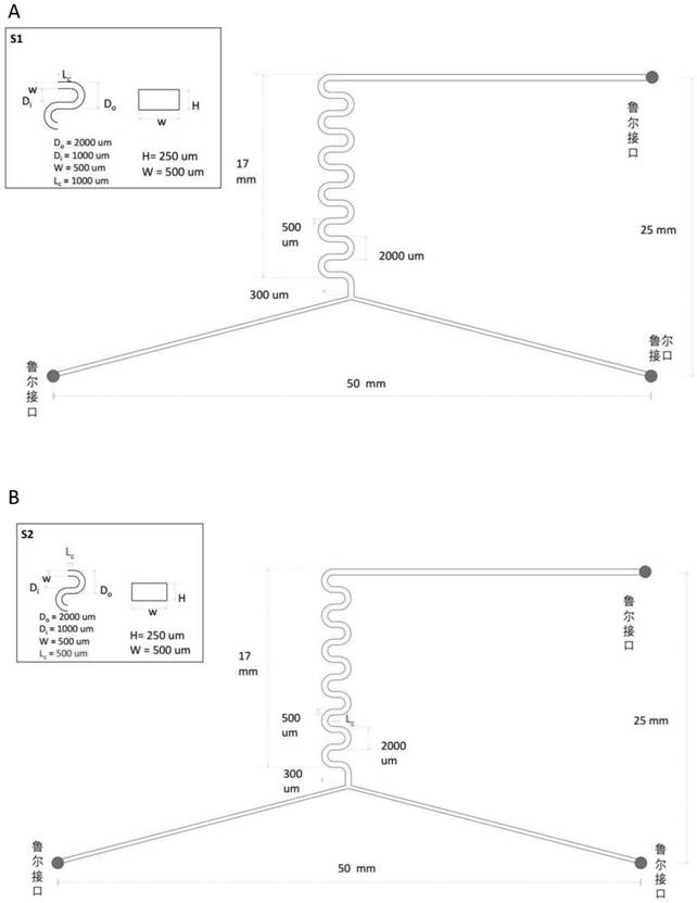
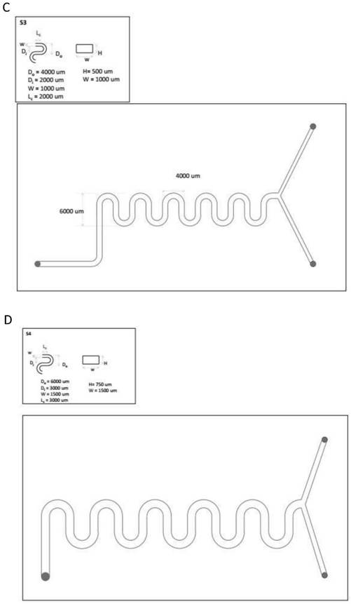
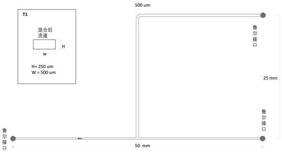
[0215] In this example, the mixing units numbered Y1, T1, S1, S2, and D-B1 in Table 1 were used to prepare the microfluidic chip. Y1 as Figure 8 shown, T1 as Figure 7 shown, S1 as Image 6 shown. The Lc of S2 and S1 is half of the Lc of S1, and other parameters are the same. D-B1 as Figure 5 shown in B.
[0216] In these five mixing units, the straight flow path in the inlet part of T1 is perpendicular to the straight flow path in the confluence part, while the other four are at a certain angle. In addition, Y1, T1, S1, and S2 use conventional rectangular cross-sections in the prior art, while D-B1 is the double-layer waveform mixing unit of the present invention.
[0217] The test method is as above " Preparation of LNPs Different flow rates were tried. Specifically, total flow rates of 1mL / min and 6mL / min were tried for all five mixing units. An additional 4mL was also tried for the onl...
Embodiment 2
[0224] Example 2. Scale-up of microstructured hybrid cells
[0225] In this embodiment, the hybrid cells numbered Y2, S3 and D-B4 in Table 1 are used as chips. These three chips are made by 200% proportional enlargement of the dimensions of Y1, S1 and D-B2 respectively. Proportional enlargement means that the length, width and height are all enlarged in the stated proportions. The angle between the entrance part and the confluence part of these three chips is the same. The difference is that Y2 is a straight line in the mixing part, S3 is a single-layer waveform mixing unit, and D-B4 is a double-layer waveform mixing unit.
[0226] The test method is as above " Preparation of LNPs ”. Different flow rates were tried. Specifically, 6 total flow rates were tried for each of the 3 mixing units: 1, 6, 12, 20, 24, 30 mL / min; also for both waveform mixing units 4 mL / min, which works well in Example 1. The statistical results of PDI, volume particle size and PDI of self-assembled ...
PUM
| Property | Measurement | Unit |
|---|---|---|
| Particle size | aaaaa | aaaaa |
Abstract
Description
Claims
Application Information