
Device and method for beam shaping and beam modulation during laser material processing

a laser material and beam modulation technology, applied in the field of devices and methods for beam shaping and beam modulation, can solve the problems of limited geometry adaptation, not being able to achieve great flexibility, and not being able to meet the general requirements of the rule, etc., and achieve the effect of great flexibility

Pending Publication Date: 2022-02-03
FRAUNHOFER GESELLSCHAFT ZUR FOERDERUNG DER ANGEWANDTEN FORSCHUNG EV
View PDF0 Cites 0 Cited by
  • Summary
  • Abstract
  • Description
  • Claims
  • Application Information

AI Technical Summary

Benefits of technology

The present invention aims to provide a device and method for laser material machining that allows for greater flexibility and efficiency. The invention allows for precise shaping of the laser beam to achieve desired energy density distribution on the workpiece surface. The device includes a beam shaping element and an optical deflection element that can be rotated to change the point of incidence and the intensity distribution of the laser beam. The device can achieve continuous material machining by using a cw laser beam source. Overall, the invention improves the efficiency and flexibility of laser material machining.

Problems solved by technology

In conventional processes with static beam geometries, this is, however, not satisfied as a rule.
It is, however, disadvantageous in this method and in similar methods that only a limited adaptation of the geometry is hereby possible that does not permit any great flexibility.

Method used


Image

  • Device and method for beam shaping and beam modulation during laser material processing
  • Device and method for beam shaping and beam modulation during laser material processing

Examples


Embodiment Construction

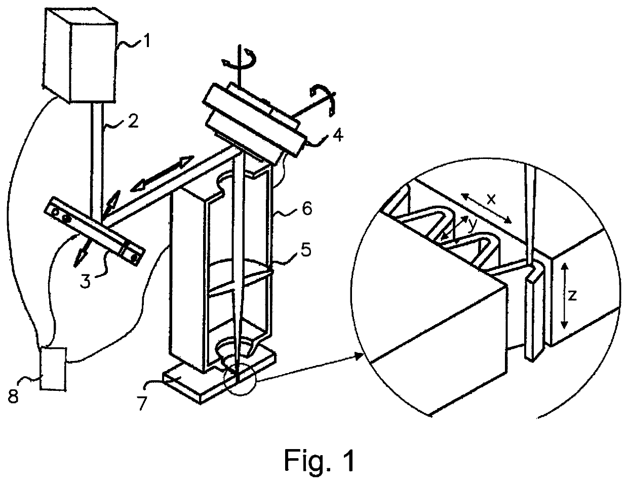
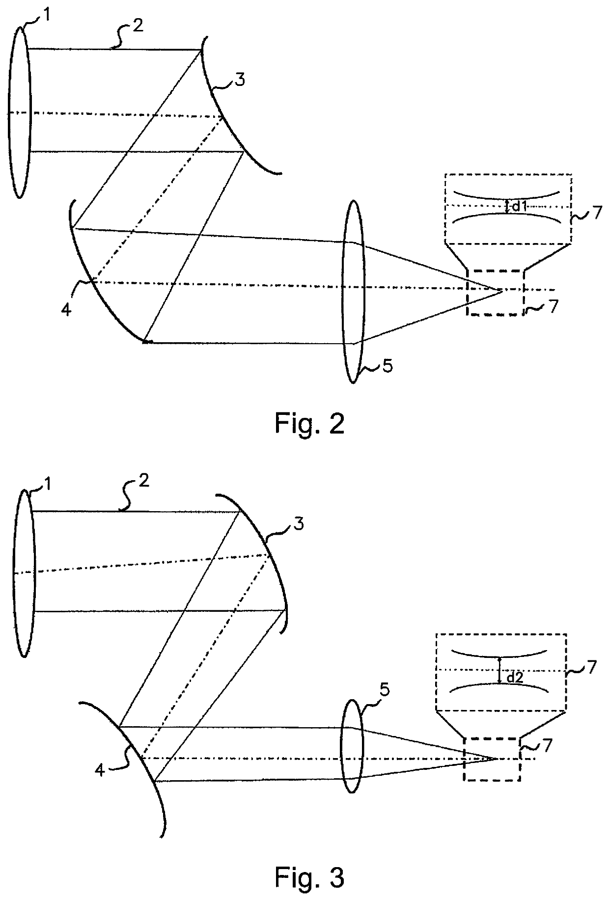
[0025]FIG. 1 shows in a schematic perspective view a device for beam shaping or beam movement. A laser beam source 1, in the present case a cw laser beam source, that is a laser beam source emitting a continuous non-pulsed beam, emits a laser beam 2 that can be emitted both in the electromagnetic wavelength range of visible radiation, infrared radiation, or ultraviolet radiation. The laser beam 2 is deflected by reflection, by 90° in the embodiment shown, in the direction of an optical deflection element 4 by a movable mirror as the beam shaping element 3.

[0026]The optical deflection element 4 is rotatable about two axes that are perpendicular to one another and is likewise a mirror in the embodiment shown. In further embodiments, the optical deflection element 4 can, however, also be made up of two mirrors. The optical deflection element 4 deflects the laser beam 2 in the direction of a workpiece surface 7 to be processed. A focusing element 5, a spherical or aspherical lens in the...


PUM

PropertyMeasurementUnit
poweraaaaaaaaaa
frequencyaaaaaaaaaa
frequencyaaaaaaaaaa

Abstract

A device and a method for beam shaping and beam movement during laser material processing with a laser beam source (1) for continuously emitting a laser beam (2), a first optical deflection element (3), a second optical deflection element (4), and an optical focusing element (5) arranged between the second optical deflection element (4) and a workpiece surface (7) to be processed. The second optical deflection element (4) is configured to displace a point of incidence of the laser beam (2) on the workpiece surface (7), and the first optical deflection element (3) is configured to alter a position of a focal plane of the laser beam (2) relative to the workpiece surface (7) by means of a translational movement and / or to change an intensity distribution within a beam cross section of the laser beam.

Description

BACKGROUND OF THE INVENTION[0001]The present invention relates to a device and to a method for beam shaping and for beam modulation on a laser material machining.[0002]In the ideal case, methods for laser material machining require a three-dimensional distribution of a laser power density adapted to a respective process at a point of action to achieve optimum machining results with respect to quality and process efficiency. In conventional processes with static beam geometries, this is, however, not satisfied as a rule.[0003]Previous approaches for adapting a power density distribution of a laser beam are based either on static approaches or with respect to a flexibility of adaptation possibilities of dynamic methods previously only usable with limitations.[0004]A method is, for example, known from DE 10 2008 053 397 A1 in which an adaptation of a section geometry is carried out by means of beam shaping. It is, however, disadvantageous in this method and in similar methods that only...

Claims


Application Information

Patent Timeline
Patent Type & Authority Applications(United States)
IPC IPC(8): H01S3/00B23K26/06
CPCH01S3/005B23K26/0648B23K26/0643B23K26/082G02B26/101G02B26/105G02B27/0983B23K26/38B23K26/242B23K26/26B23K26/046B23K26/14
Inventor WETZIG, ANDREASMAHRLE, ACHIMHERWIG, PATRICKHAUPTMANN, JANEBERHARDT, RAMONABOETTNER, PAUL
Owner FRAUNHOFER GESELLSCHAFT ZUR FOERDERUNG DER ANGEWANDTEN FORSCHUNG EV
Learn More