Metal plate rolling compounding method, rolling forming composite plate and roller

A technology for rolling composite and metal sheets, applied in the directions of metal rolling, metal rolling, rolls, etc., can solve the problems of cracking, the connection and falling off of composite plates, etc., to improve rolling efficiency, not easy to separate, and increase the contact area of ​​​​fitting Effect

Pending Publication Date: 2022-05-27
HENAN UNIV OF SCI & TECH
View PDF2 Cites 0 Cited by
  • Summary
  • Abstract
  • Description
  • Claims
  • Application Information

AI Technical Summary

Problems solved by technology

[0007] The purpose of the present invention is to provide a metal sheet rolling composite method to solve the technical problem that the composite sheet rolled by the composite sheet rolling method in the prior art is easy to connect, fall off or crack in the stacking direction

Method used


Image

  • Metal plate rolling compounding method, rolling forming composite plate and roller
  • Metal plate rolling compounding method, rolling forming composite plate and roller
  • Metal plate rolling compounding method, rolling forming composite plate and roller

Examples


Embodiment 1

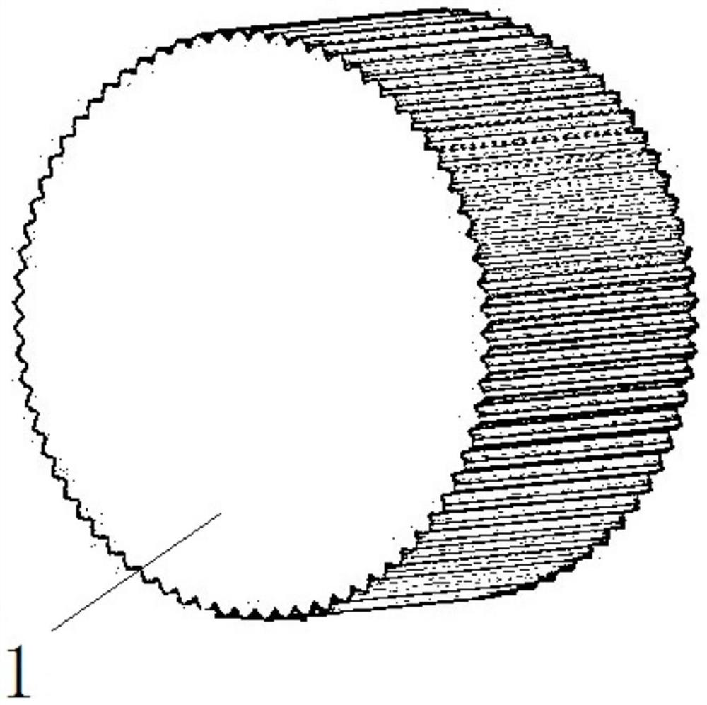
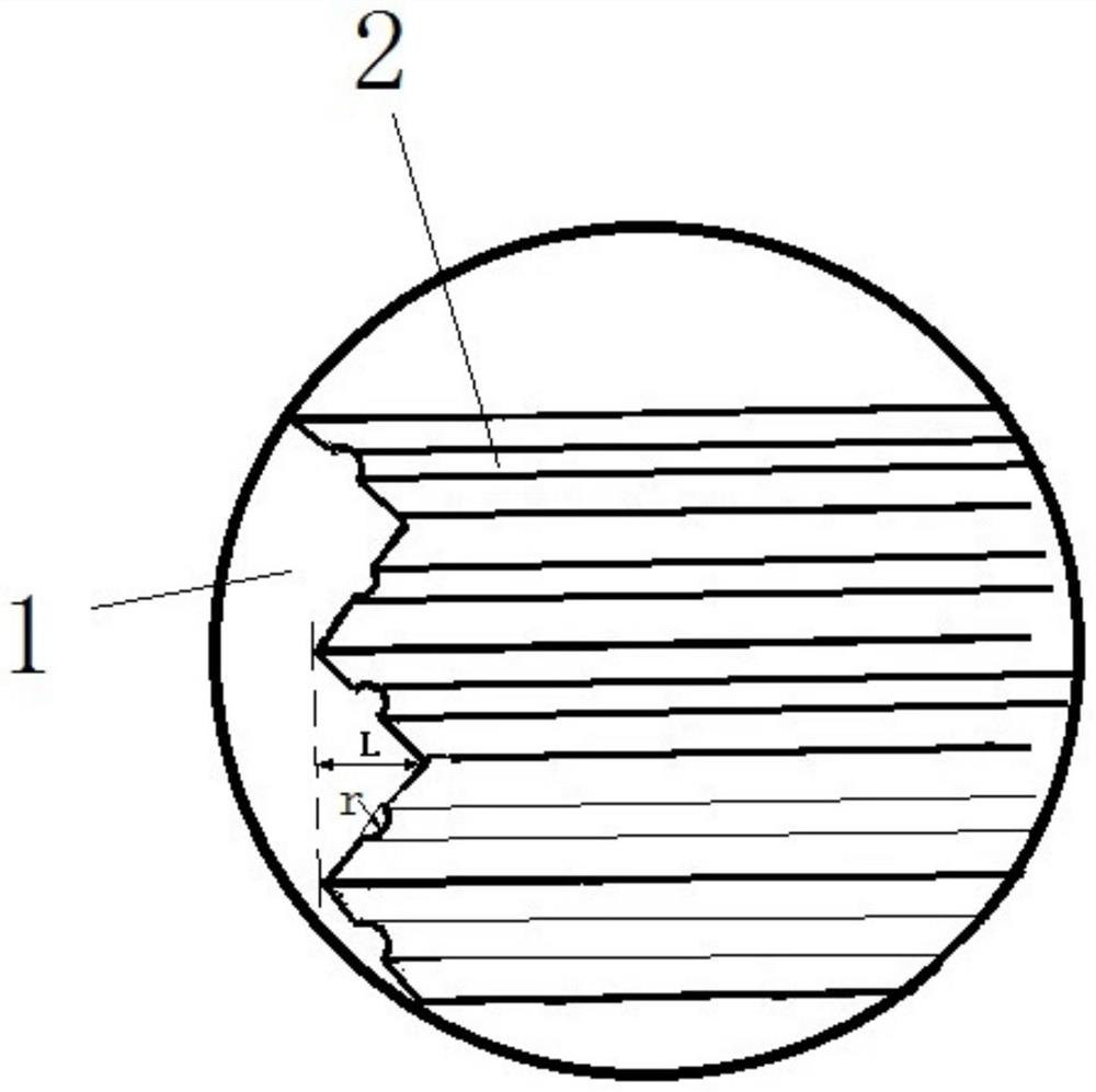
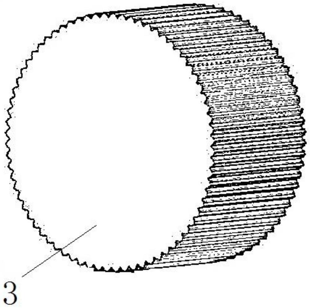
[0068] In this embodiment, the method of rolling and compositing the metal plate is completed by rolling the metal plate with rollers, such as figure 1 and image 3 As shown, the roll has a cylindrical cylindrical structure, the material of the roll is high-strength hard alloy steel with high performance requirements, and the roll is assembled on the rolling mill when in use. The roll includes a flat roll 11 with a flat outer peripheral surface and a corrugated roll with roll teeth on the outer peripheral surface. The roll teeth on the corrugated roll extend in the axial direction of the roll. After the rolled metal plate is in contact with the roll, with the rotation of the roll, the roll The teeth can roll a corrugated slope on the metal plate, and the flat roll 11 can roll a flat plane on the metal plate. Among them, the corrugated roll includes two different roll tooth structures, such as Figure 1 to Figure 10 As shown, one of the corrugated rollers is a raised corrugat...

specific Embodiment 2

[0078] The difference from Example 1 is that in Example 1, the two opposite slopes in the corrugated groove of the first corrugated surface 6 are formed with clamping grooves 9, and the two opposite corrugated edges on the second corrugated surface 8 are formed. Pre-card protrusions 10 are formed on the slope surface. In this embodiment, the number of roller protrusions on the grooved corrugated roller can be reduced, and the roller protrusions are arranged on the roller teeth at intervals, that is, the roller protrusions are arranged on the tooth surface every time a certain number of roller teeth are separated. The grooves on the first corrugated surface are separated by a certain number of corrugated edges. At this time, corresponding to the groove processing corrugated roller, the number of grooves on the convex processing corrugated roller is correspondingly reduced, and the grooves are arranged at intervals on the roller teeth. For every certain number of roller teeth, t...

specific Embodiment 3

[0080] The difference from Embodiment 1 is that in Embodiment 1, the clamping grooves 9 on two opposite slopes in the corrugated groove correspond one-to-one and the opposite slopes are symmetrically arranged. In this embodiment, the heights of the clamping grooves on the opposite slopes in the corrugated groove from the bottom of the corrugated groove are different.


PUM


Abstract

The invention relates to the technical field of composite plate rolling, and aims to provide a metal plate rolling compounding method, a rolled composite plate and a roller so as to improve the interlayer bonding strength of the composite plate rolled by the roller. The metal plate rolling compounding method adopts a roller to roll a composite plate, and comprises the following steps: 1) rolling a first corrugated surface on a first metal plate, rolling a second corrugated surface on a second metal plate, matching the first corrugated surface with the second corrugated surface, forming a clamping groove on the first corrugated surface, and forming a bulge on the second corrugated surface; (2) the first metal plate and the second metal plate are stacked together, so that the protrusions are clamped into the clamping grooves, and the clamping grooves can limit the protrusions to be separated in the stacking direction of the two metal plates; (3) the first metal plate and the second metal plate are pre-fixed and then rolled to form a composite plate; the roller comprises a flat roller and a corrugated roller, and the corrugated roller comprises a clamping groove processing corrugated roller with bulges on the tooth surfaces of roller teeth and a bulge processing corrugated roller with grooves on the tooth surfaces of the roller teeth.

Description

technical field [0001] The invention relates to the technical field of clad plate rolling, in particular to a roll and a method for rolling a clad plate. Background technique [0002] At present, metal clad plates composed of different materials have been widely used in various industries, and the metal clad material technology can give play to the respective advantages of the component materials and realize the optimal allocation of the resources of each component material. Among them, each group of raw materials includes metal sheets waiting to be rolled. In the prior art metal clad plate processing technology, a rolling mill is often used to roll the clad plate and the base plate, and then the clad plate and the base plate are flatly stacked and assembled to roll and press metal clad plates of different thicknesses. [0003] In the prior art, the method of using a rolling mill to roll a composite plate has been used in the field of rolling technology. For example, the ut...

Claims


Application Information

Patent Timeline
IPC IPC(8): B21B27/02B21B1/22
CPCB21B27/021B21B1/227B21B2267/18
Inventor 皇涛宋克兴赵家鑫周延军刘海涛李韶林张彦敏国秀花程楚
Owner HENAN UNIV OF SCI & TECH
Why Eureka
Try Eureka