Variable-stiffness variable-damping magnetorheological fluid vibration reduction boring bar

A technology of magnetorheological fluid and variable damping, applied to boring bars and other directions, can solve the problems of boring bar machining accuracy and machining efficiency, and achieve the effects of reducing boring bar vibration, changing damping, and improving machining efficiency.

Active Publication Date: 2022-05-27
HARBIN UNIV OF SCI & TECH
View PDF14 Cites 5 Cited by
  • Summary
  • Abstract
  • Description
  • Claims
  • Application Information

AI Technical Summary

Problems solved by technology

[0004] In order to solve the problem that the vibration generated in the processing process of the existing boring bar affects the processing accuracy and processing efficiency, the present invention further proposes a magnetorheological fluid damping boring bar with variable stiffness and variable damping

Method used


Image

  • Variable-stiffness variable-damping magnetorheological fluid vibration reduction boring bar
  • Variable-stiffness variable-damping magnetorheological fluid vibration reduction boring bar
  • Variable-stiffness variable-damping magnetorheological fluid vibration reduction boring bar

Examples


specific Embodiment approach 1

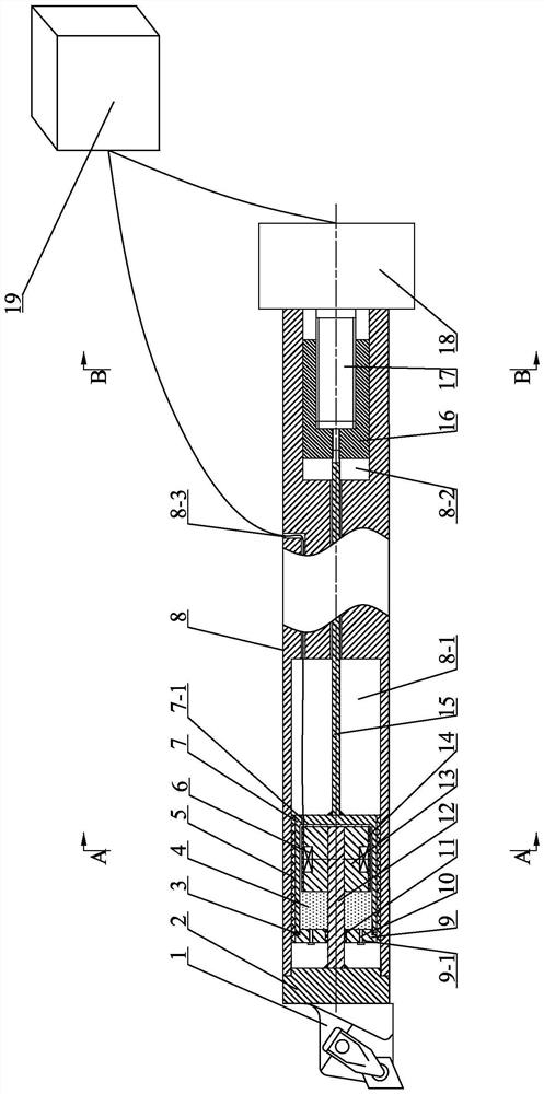
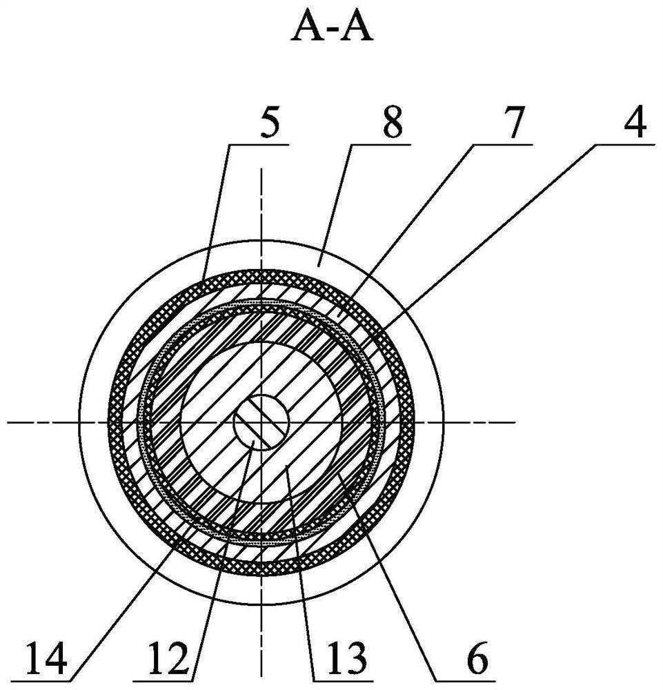
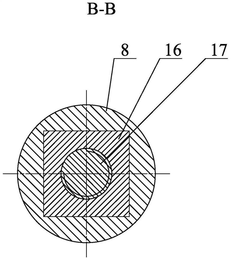
[0023] Embodiment 1: Combining Figure 1 to Figure 5 Illustrating this embodiment, a variable stiffness variable damping magnetorheological fluid vibration damping boring bar described in this embodiment includes a cutter head connecting block 2, a coil 6, a cylinder block 7, a rod body 8, a cylinder head 9, a cantilever beam 12, Iron core 13, telescopic rod 15, slider 16, lead screw 17, stepper motor 18 and control system 19, the middle of the front end face of the rod body 8 is provided with a boring bar cavity 8-1, and the rear side of the cutter head connecting block 2 The end is inserted into the cavity mouth of the boring bar cavity 8-1, the front end of the cantilever beam 12 is vertically fixed to the middle of the rear end face of the cutter head connecting block 2, and the cylinder body 7 is inserted into the boring bar cavity 8-1. The front end of the cylinder block 7 is fixed with the cylinder head 9 , the rear end of the cantilever beam 12 passes through the cylin...

specific Embodiment approach 2

[0029] Specific implementation mode 2: Combining Figure 1 to Figure 5 Illustrating this embodiment, the outer side of the iron core 13 described in this embodiment is sheathed with a rubber sleeve 1 14 . Other compositions and connection methods are the same as those in the first embodiment.

[0030] The rubber sleeve 14 is inserted into the outer side of the iron core 13 to protect the coil 6 from being affected by the magnetorheological fluid 4 .

specific Embodiment approach 3

[0031] Specific implementation three: combination Figure 1 to Figure 5 Describing the present embodiment, the outer side of the cylinder block 7 described in the present embodiment is sheathed with a rubber sleeve 2 5 . Other compositions and connection methods are the same as those in the first embodiment.

[0032] In this embodiment, the second rubber sleeve 5 is fixedly connected to the outer side of the cylinder block 7 to ensure that the entire cylinder block 7 can slide in the boring bar cavity 8-1.


PUM


Abstract

The invention discloses a variable-rigidity variable-damping magnetorheological fluid vibration reduction boring bar, and relates to the technical field of cutting machining. The problem that vibration generated in the machining process of an existing boring rod affects the machining precision and the machining efficiency is solved. The boring rod comprises a tool bit connecting block, a coil, a cylinder body, a rod body, a cylinder cover, a cantilever beam, an iron core, a telescopic rod, a sliding block, a lead screw, a stepping motor and a control system, the cylinder body is inserted in a cavity of the boring rod, the iron core is arranged in the cylinder body, a gap is formed between the iron core and the inner side wall of the cylinder body, the iron core is fixedly connected to the end of the rear end of the cantilever beam in a sleeving mode, and the coil is embedded in the outer side of the iron core; the cylinder body is filled with magnetorheological fluid, the telescopic rod is inserted into the rod body, the front end of the telescopic rod is arranged in the boring rod cavity and perpendicularly and fixedly connected with the rear end of the cylinder body, the front end of the lead screw is in threaded connection with the rear end of the sliding block, the rear end of the lead screw is fixedly connected with an output shaft of the stepping motor, and the rear end of the telescopic rod is arranged in the groove and fixedly connected with the front end of the sliding block. The boring cutter is used for boring.

Description

technical field [0001] The invention relates to the technical field of cutting processing, in particular to a variable stiffness variable damping magnetorheological fluid vibration damping boring bar. Background technique [0002] In metal cutting processing, inner hole processing accounts for about 33% of the total processing, among which ultra-deep hole processing mostly involves major fields such as aerospace and energy equipment. [0003] Boring tools are widely used in deep hole machining. However, due to the low rigidity of the cantilever beam structure of the boring bar, vibration often occurs when the long diameter of the boring bar is relatively large, and during the boring process, the boring bar needs to extend into the To process inside the workpiece, the working conditions are closed, and the real-time machining state of the boring bar cannot be directly observed. The contact between the boring bar and the workpiece is more complicated under the action of vibrat...

Claims


Application Information

Patent Timeline
Patent Type & Authority Applications(China)
IPC IPC(8): B23B29/02
CPCB23B29/022Y02P70/10
Inventor 刘强周强马晶范吉庆李定坤
Owner HARBIN UNIV OF SCI & TECH
Why Eureka
Try Eureka