Automatic soldering machine teaching programming method based on model and numerical control drilling file

A programming method and automatic welding technology, applied in the direction of program control manipulator, manipulator, welding equipment, etc., can solve problems such as the inability to guarantee the consistency of coordinate values, affecting the accuracy of the correspondence between image coordinates and physical coordinates, and affecting the efficiency of teaching and programming.

Pending Publication Date: 2022-05-27
大连爱智控制系统有限公司
View PDF2 Cites 2 Cited by
  • Summary
  • Abstract
  • Description
  • Claims
  • Application Information

AI Technical Summary

Problems solved by technology

The three-axis automatic soldering machine moves on the X-axis (left and right), Y-axis (front-to-back), and Z-axis (up and down), and there will be welding dead ends
The disadvantages of this method are: first, the established coordinate transformation relationship is the corresponding relationship between the welding layer image in the Gerber file graphics and the actual solder joints, and ther

Method used


Image

  • Automatic soldering machine teaching programming method based on model and numerical control drilling file
  • Automatic soldering machine teaching programming method based on model and numerical control drilling file
  • Automatic soldering machine teaching programming method based on model and numerical control drilling file

Examples


Embodiment Construction

[0081] The present invention will be further described below in conjunction with the accompanying drawings.

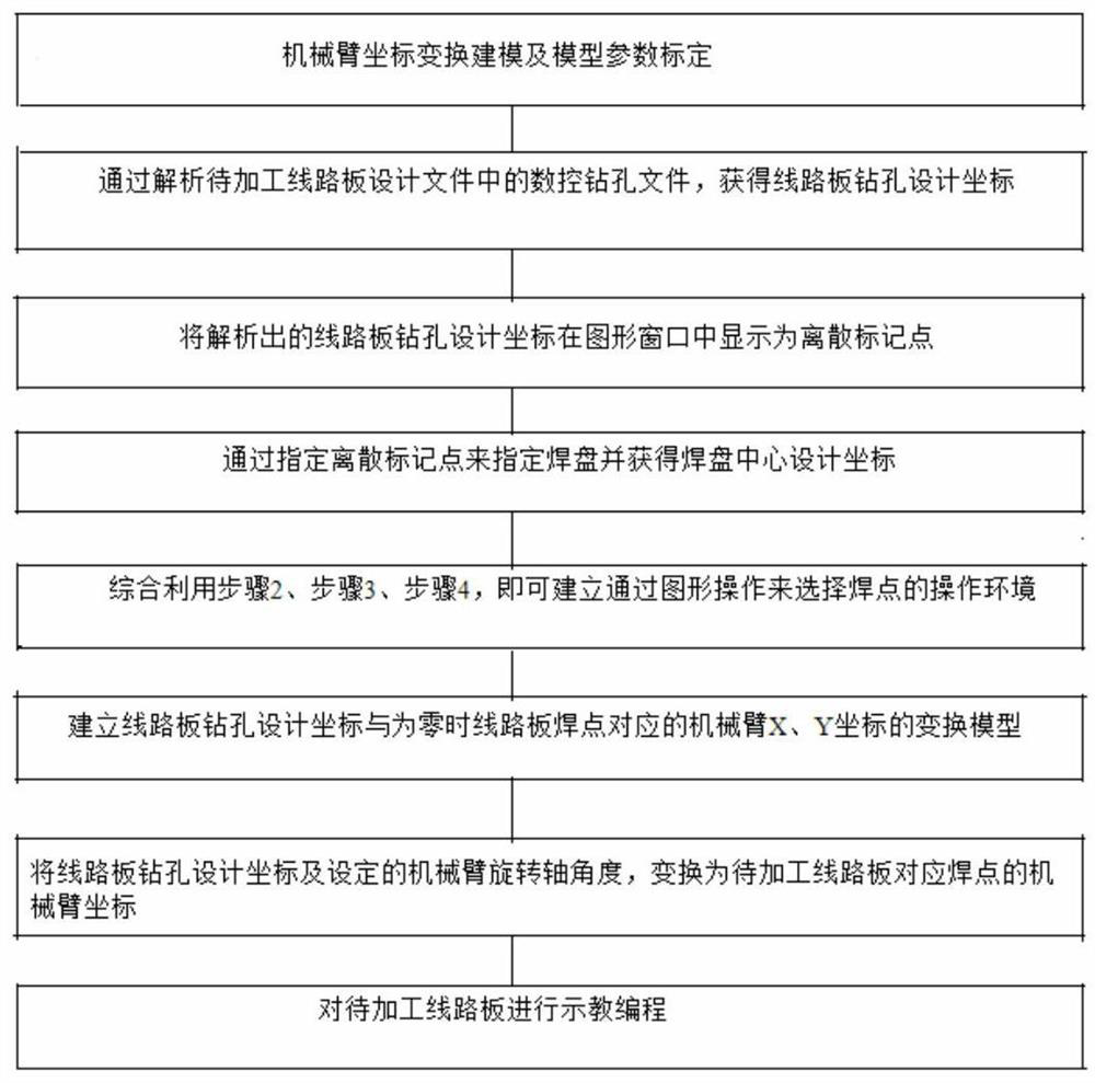
[0082] like figure 1 As shown in the figure, a teaching programming method for an automatic soldering machine based on a model and a CNC drilling file includes the following steps:

[0083] Step 1. Coordinate transformation modeling and model parameter calibration of the robotic arm, including the following sub-steps:

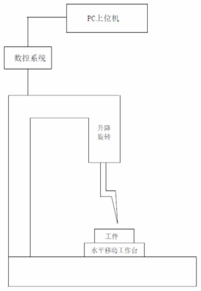
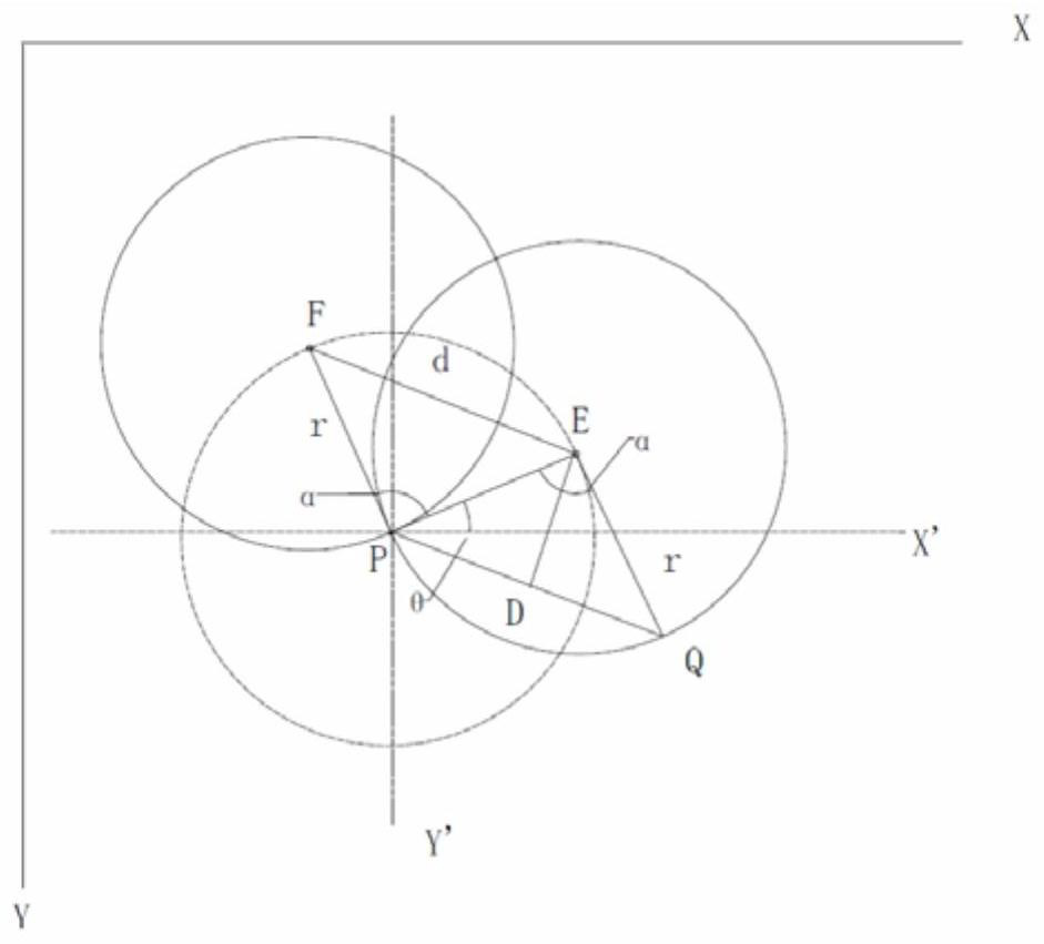
[0084] (a) Modeling of the coordinate transformation of the robotic arm. For an automatic soldering machine with a rotating axis, when the circuit board is fixed on the automatic soldering machine table by a fixture, the coordinate of the robotic arm corresponding to a solder joint on the circuit board is represented by (X , Y, Z, α) T , ie Cartesian coordinates (X, Y, Z) T Determined with the angle coordinate α of the rotation axis, the plane where the circuit board is located is parallel to the XY plane of the robot arm coordinate system through th...


PUM


Abstract

The invention belongs to the technical field of automatic soldering of soldering machines, and relates to an automatic soldering machine teaching programming method based on a model and a numerical control drilling file, which comprises the following steps: (1) carrying out mechanical arm coordinate transformation modeling and model parameter calibration, (2) analyzing a numerical control drilling file in a to-be-processed circuit board design file to obtain circuit board drilling design coordinates, and (3) carrying out numerical control drilling on the circuit board drilling design coordinates. The method comprises the steps of (1) analyzing circuit board drilling design coordinates, (2) analyzing the circuit board drilling design coordinates, (3) displaying the analyzed circuit board drilling design coordinates as discrete mark points in a graphic window, (4) appointing a bonding pad by appointing the discrete mark points and obtaining bonding pad center design coordinates, and (5) establishing an operation environment for selecting the bonding pads through graphic operation by utilizing the steps (2), (3) and (4). (6) establishing a transformation model of the circuit board drilling design coordinates and the mechanical arm coordinates corresponding to the circuit board welding spots, (7) transforming the circuit board drilling design coordinates and the set mechanical arm rotating shaft angle into the mechanical arm coordinates of the corresponding welding spots of the circuit board to be processed, and (8) carrying out teaching programming on the circuit board to be processed. According to the automatic soldering machine mechanical arm coordinate transformation model with the rotating shaft, transformation from circuit board drilling design coordinates to mechanical arm coordinates corresponding to circuit board welding spots is established, a solder tip automatically reaches the specified welding spot position in a specified posture in a graphic operation mode, and teaching programming efficiency is improved.

Description

technical field [0001] The invention relates to an automatic soldering machine teaching and programming method based on a model and a numerical control drilling file, and belongs to the technical field of automatic soldering of soldering machines. Background technique [0002] The automatic soldering machine is mainly used in the electronics manufacturing industry, especially for the soldering of connectors in the SMT back-end process of the mixed circuit board. The automatic soldering machine includes two parts: the soldering system and the robotic arm. The soldering system mainly includes automatic tin feeding mechanism and welding torch (temperature control, heating element, soldering iron head). There are mainly three-axis systems and four-axis systems for robotic arms. The three-axis automatic soldering machine moves the X-axis (left and right), Y-axis (front and rear), and Z-axis (up and down), and there will be welding dead spots. The four-axis automatic soldering ...

Claims


Application Information

Patent Timeline
IPC IPC(8): B23K3/00B23K3/08B25J9/16
CPCB23K3/00B23K3/08B25J9/163B25J9/1679Y02P90/02
Inventor 仲崇权高大鹏孙红涛邢志鹏董兆罡
Owner 大连爱智控制系统有限公司
Why Eureka
Try Eureka