
Glue injection opening mold with foot side edge flash removal function

A technology for injection molds and injection ports, which is applied in the field of injection port molds with foot side overflow removal, and can solve problems such as poor appearance and weldability, expensive mold costs, laser attenuation and missing cuts, etc.

Pending Publication Date: 2022-05-27
JIANGSU BAO PU LAY SEMICON
View PDF0 Cites 0 Cited by
  • Summary
  • Abstract
  • Description
  • Claims
  • Application Information

AI Technical Summary

Problems solved by technology

[0003] The defects of the existing injection port molds for clearing the overflow on the side of the foot are: for the removal of the overflow, there are two traditional solutions, one is that the precision of the mold is very high, and the tolerance is + / -0.025mm In order to suppress and reduce the gap between the frame and the injection mold, thereby reducing the formation of side flashes, the high precision requirements make the cost of the whole set of molds expensive and not conducive to maintenance and maintenance, nor can the length of side flashes be guaranteed If it is less than 0.1mm, it will bring complaints of poor appearance and solderability. The other is to change the design direction of the injection port and inject resin along both ends of the lead, so that the entire frame will have the same frame on both sides of the lead The formation of thick flashing requires adding a laser de-flashing process in the subsequent process, investing in equipment and manpower costs, and this process will cause laser attenuation and missing cuts. and complaints of poor solderability

Method used


Image

  • Glue injection opening mold with foot side edge flash removal function
  • Glue injection opening mold with foot side edge flash removal function
  • Glue injection opening mold with foot side edge flash removal function

Examples


Embodiment Construction

[0019] The technical solutions in the embodiments of the present invention will be clearly and completely described below with reference to the accompanying drawings in the embodiments of the present invention. Obviously, the described embodiments are only a part of the embodiments of the present invention, but not all of the embodiments. Based on the embodiments of the present invention, all other embodiments obtained by those of ordinary skill in the art without creative efforts shall fall within the protection scope of the present invention.

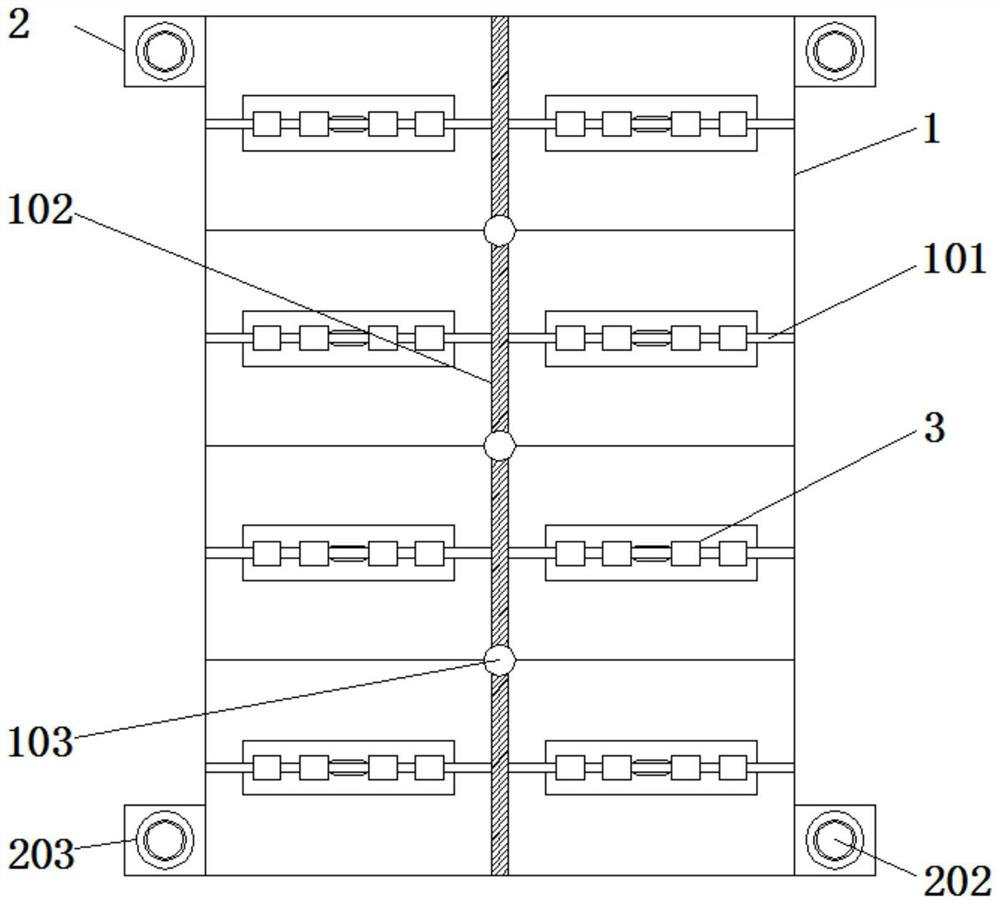
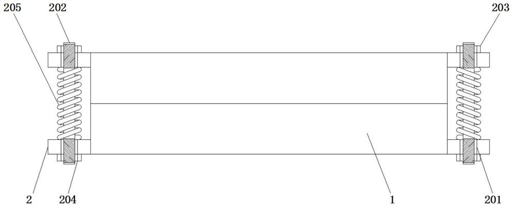
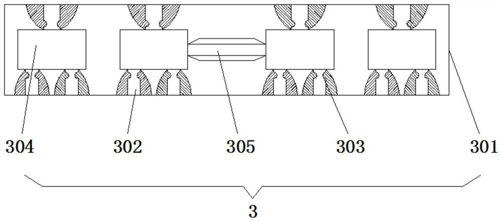
[0020] The present invention provides the following technical solutions: a plastic injection port mold with foot side overflow removal, which can effectively set the overflow removal treatment on the plastic injection port mold during use, and a single-window mechanism 3 is added. Please refer to Figure 1-4 , including a plastic injection mold 1, a plurality of groups of branch pipes 101 are installed above and below the surface of th...


PUM


Abstract

The invention discloses a glue injection opening mold with a foot side edge flash removal function in the technical field of glue injection mold production parts, the glue injection opening mold comprises a glue injection mold, a plurality of sets of branch pipelines are installed above and below the surface of the glue injection mold, a main pipeline is installed between the opposite sides of the two sets of branch pipelines, and the main pipeline is communicated with the glue injection mold. A glue injection opening is formed in the front end face of each main pipeline, fixing plates are installed above and below the outer walls of the two sides of each glue injection mold, and a single-window mechanism is installed at the bottom of each branch pipeline. The fan-shaped retaining dam structures are respectively arranged at the two ends of the pin on the tooth groove of the mold insert, when resin flows to the two sides of the pin, the movement path can be effectively cut off, very thin slitter edges are formed, and overflow materials on the side edges can be easily removed through an electroplating water jet cutter in the subsequent process.

Description

technical field [0001] The invention relates to the technical field of plastic injection mold production parts, in particular to a plastic injection port mold with a foot side overflow removal. Background technique [0002] Molds, various molds and tools used in industrial production to obtain the desired products by injection molding, blow molding, extrusion, die casting or forging, smelting, stamping and other methods. In a nutshell, a mold is a tool used to make a shaped item, this tool is made up of various parts, and different molds are made up of different parts. It mainly realizes the processing of the shape of the article by changing the physical state of the formed material. [0003] The defects of the existing plastic injection mold for removing the overflow on the side of the foot are: for the removal of the overflow, there are two traditional solutions. One is that the precision of the mold is very high and the tolerance is + / -0.025mm. In this way, the gap betw...

Claims


Application Information

Patent Timeline
IPC IPC(8): B29C45/26B29C45/27
CPCB29C45/2602B29C45/2608B29C45/2669B29C45/2708B29C2045/2671B29C2045/2683B29C2045/2709B29C2045/2716
Inventor 张帆
Owner JIANGSU BAO PU LAY SEMICON
Learn More