Conductive semi-rigid bearing

A semi-rigid, bearing technology, applied in the field of bearings, can solve the problems that it is difficult to achieve zero clearance processing, reduce the use effect of bearings, and not require high load-bearing capacity, so as to avoid deviation, reduce bearing resistance, and save processing costs. Effect

Active Publication Date: 2022-05-27
C&U CO LTD +2
View PDF5 Cites 0 Cited by
  • Summary
  • Abstract
  • Description
  • Claims
  • Application Information

AI Technical Summary

Problems solved by technology

[0002] The commonly used automotive steering column bearings usually use ordinary ball bearings. Most of these bearings are thin-walled series bearings. The working environment of automotive steering column bearings is: the speed is low, generally around 100rpm, The requirements for bearing capacity are not high, both axial and radial loads are present, and the temperature of the working environment is not high, generally around -40-80°C. With the development of the automobile industry, the requirements for bearings are getting higher and higher. It is also more special. Most customers require that the steering column bearings of automobiles must have zero clearance to meet the purpose of small axial movement. However, it is difficult for our conventional ball bearings to achieve zero clearance during processing. Reduce the use of bearings

Method used


Image

  • Conductive semi-rigid bearing
  • Conductive semi-rigid bearing
  • Conductive semi-rigid bearing

Examples


Embodiment Construction

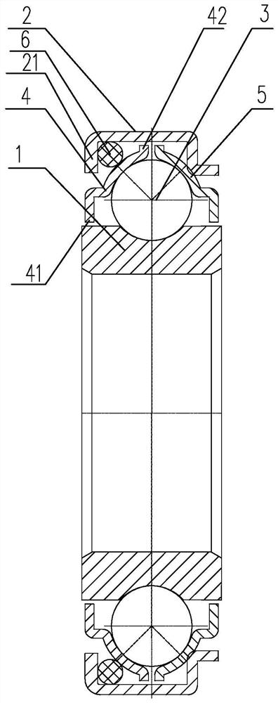
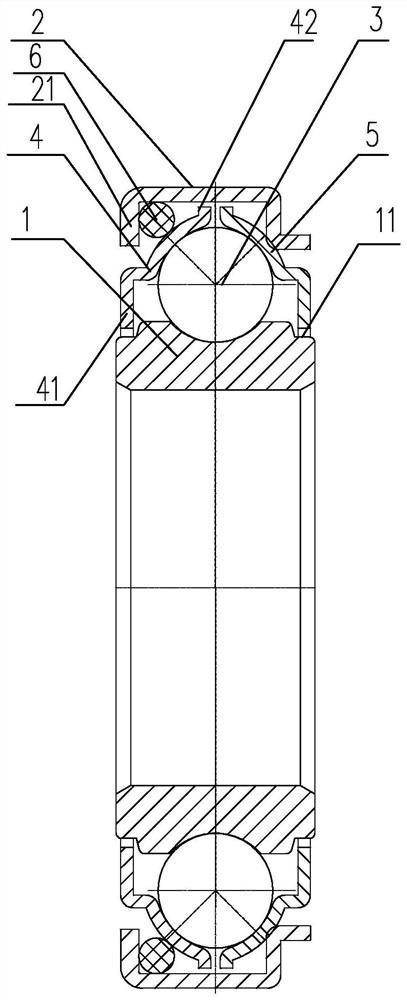
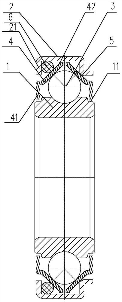
[0019] The first embodiment of the conductive semi-rigid bearing of the present invention is figure 1 Shown: it includes an inner ring 1 and an outer ring 2, a raceway is provided on the outer wall of the inner ring 1, the roller 3 is arranged on the raceway, and a first roller is arranged between the outer ring 2 and the roller 3 A raceway ring 4 and a second raceway ring 5, the first raceway ring 4 and the second raceway ring 5 are respectively arranged on both sides of the roller 3, the first raceway Including a fitting portion for fitting on the outer peripheral surface of the roller 3, the fitting portion is arranged in the form of an arc surface, and an elastic rubber ring 6 is provided in conflict between one end of the outer ring 2 and the first raceway ring 4 , the outer ring 2 is formed with a conflicting portion corresponding to the position of the second raceway ring 5 , and the conflicting portion abuts on the second raceway ring 5 . The beneficial effects of thi...


PUM


Abstract

The invention discloses a conductive semi-rigid bearing which comprises an inner ring, a roller path is arranged on the outer wall of the inner ring, a roller is arranged on the roller path, the conductive semi-rigid bearing further comprises an outer ring, a first roller path ring and a second roller path ring are arranged between the outer ring and the roller, and the first roller path ring and the second roller path ring are arranged on the two sides of the roller respectively. Each of the first roller path ring and the second roller path ring comprises a fitting part used for abutting against the peripheral surface of a roller, an elastic rubber ring is arranged between one end of the outer ring and the first roller path ring in an abutting manner, an abutting part is formed on the outer ring corresponding to the position of the second roller path ring, and the abutting part abuts against the second roller path ring. The bearing is simple in structure, reasonable in layout and convenient to process, and can meet the use requirements of lower electric conduction or resistance of the bearing.

Description

technical field [0001] The invention relates to the technical field of bearings, in particular to a conductive semi-rigid bearing. Background technique [0002] The existing commonly used automobile steering column bearings usually use ordinary ball bearings. Most of these bearings are mainly thin-walled series bearings, while the working environment of automobile steering column bearings is: the rotation speed is low, generally around 100rpm, The bearing capacity is not high, the axial and radial loads are both, and the temperature of the working environment is not high, generally around -40 to 80 ° C. With the development of the automotive industry, the requirements for bearings are also getting higher and higher. It is also more and more special. Most customers require that the steering column bearing in the automobile must have 0 clearance to meet the purpose of small axial movement, while our conventional ball bearings are difficult to achieve 0 clearance during process...

Claims


Application Information

Patent Timeline
Patent Type & Authority Applications(China)
IPC IPC(8): F16C33/60F16C33/58F16C33/78F16C27/06F16C27/04F16C41/00
CPCF16C33/60F16C33/583F16C33/585F16C33/7806F16C27/066F16C41/002F16C2326/24
Inventor 李新旺
Owner C&U CO LTD
Why Eureka
Try Eureka