Eureka AIR delivers breakthrough ideas for toughest innovation challenges, trusted by R&D personnel around the world.

Damping shock absorber

A shock absorber and damping technology, applied in the field of damping shock absorbers, can solve the problem of a single shock absorption direction of the damping shock absorber, and achieve the effects of increasing energy consumption, convenient processing, and increasing energy consumption capacity.

Pending Publication Date: 2022-05-27
NORTH CHINA UNIV OF WATER RESOURCES & ELECTRIC POWER
View PDF1 Cites 0 Cited by
  • Summary
  • Abstract
  • Description
  • Claims
  • Application Information

AI Technical Summary

Problems solved by technology

[0005] The purpose of the present invention is to provide a damping shock absorber to solve the technical problem that the existing damping shock absorber has a relatively single vibration reduction direction

Method used


Image

  • Damping shock absorber
  • Damping shock absorber
  • Damping shock absorber

Examples


Embodiment 1

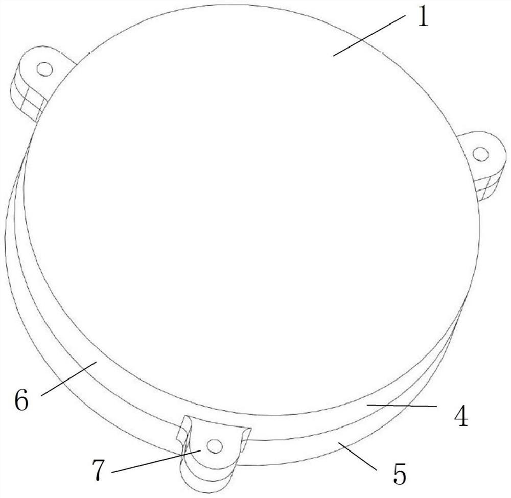
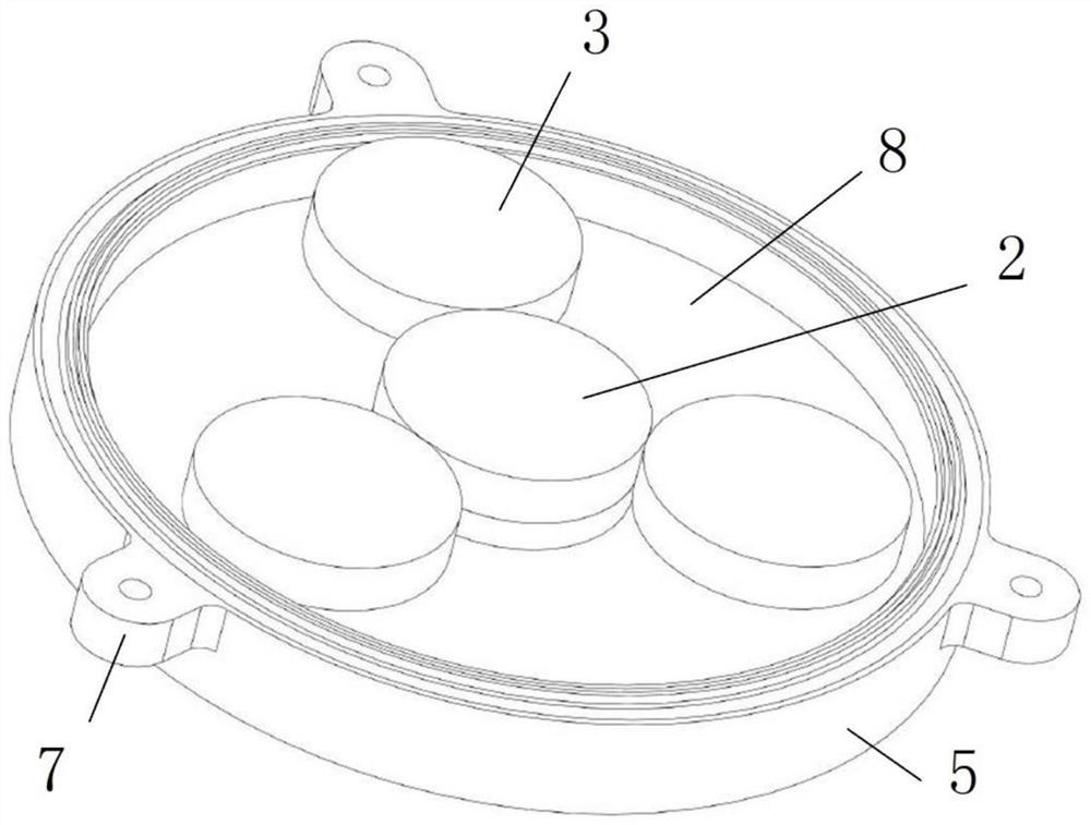
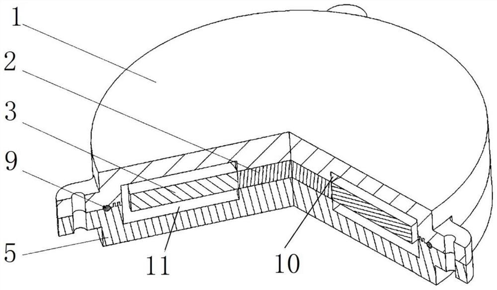
[0039] like Figure 1 to Figure 3 As shown, the shock absorber includes a housing 1 , a fixed permanent magnet 2 and an energy dissipation permanent magnet 3 .

[0040] The housing 1 is a non-magnetically conductive housing made of a non-magnetically conductive material. The housing 1 includes a first housing 4 and a second housing 5. Both the first housing 4 and the second housing 5 include a circular main housing 6 And the connecting lugs 7 arranged around the outer circumferential surface of the main casing 6, there are three connecting lugs 7 on the main casing 6 and are arranged at equal intervals, and the bolt holes for the fastening bolts to pass through are provided on the connecting lugs 7. After the fixing bolts pass through the bolt holes on the corresponding connecting ears 7 on the first shell 4 and the second shell 5 , the nuts are then screwed to realize the fast connection of the first shell 4 and the second shell 5 . The first casing 4 and the second casing 5...

Embodiment 8

[0054] Embodiment 8 of the damping shock absorber of the present invention is different from Embodiment 1 in that the three energy-consuming permanent magnets in Embodiment 1 constitute an energy-consuming permanent magnet group. In this embodiment, the energy-consuming permanent magnets are There are two sets of energy-consuming permanent magnets, and the two sets of energy-consuming permanent magnets are arranged at intervals in the axial direction of the fixed permanent magnets. Or in other embodiments, there are three, four or more energy-dissipating permanent magnet groups, and the energy-dissipating permanent magnet groups are arranged at intervals in the axial direction of the fixed permanent magnets.

[0055] Embodiment 9 of the damping shock absorber of the present invention is different from Embodiment 1 in that, as Figure 4 As shown, the outer circumferential surfaces of the fixed permanent magnet 2 and the energy-consuming permanent magnet 3 are provided with a fr...


PUM


Abstract

The invention relates to the field of shock absorbers, in particular to a damping shock absorber. The damping shock absorber comprises a shell and a fixed permanent magnet fixed in the shell, the shell is a non-magnetic shell, an energy-consuming permanent magnet is further arranged in the shell, the fixed permanent magnet and the energy-consuming permanent magnet attract each other, the energy-consuming permanent magnet and the fixed permanent magnet are cylinders with cambered peripheral surfaces, the axial direction of the energy-consuming permanent magnet is the same as that of the fixed permanent magnet, and the axial direction of the energy-consuming permanent magnet is the same as that of the fixed permanent magnet. The energy consumption permanent magnet is attracted to the outer circumferential face of the fixed permanent magnet and can move in the circumferential direction of the fixed permanent magnet, a movable cavity is formed in the shell, and the movable cavity is annular and allows the energy consumption permanent magnet to move in the circumferential direction of the fixed permanent magnet. When the damping shock absorber is used for carrying out vibration reduction on a vibration reduction object, the vibration direction of the vibration object can be any direction of the plane where the energy dissipation permanent magnet and the fixed permanent magnet are located, and the problem that an existing damping shock absorber is single in vibration reduction direction is solved.

Description

technical field [0001] The invention relates to the field of shock absorbers, in particular to a damping shock absorber. Background technique [0002] The long and straight flexible accessories such as the solar panels of the satellites and the robotic arms of the space station are easy to vibrate in the cosmic solar wind or during attitude adjustment. The damping shock absorber is a passive shock absorber, which is sensitive to inertial force and has a simple structure. , small size, no external excitation, and stable use, so it is very suitable for low-frequency and small-amplitude vibration reduction in aerospace and military large-scale equipment. [0003] The Chinese utility model patent with the authorization announcement number CN214221874U discloses a drawer-type magnetic liquid damping shock absorber, the magnetic liquid damping shock absorber includes a casing, a first permanent magnet, a second permanent magnet, a third permanent magnet, a third permanent magnet, ...

Claims


Application Information

Patent Timeline
IPC IPC(8): F16F6/00F16F7/10F16F13/00
CPCF16F6/005F16F7/1034F16F7/1022F16F13/002F16F2222/06F16F2222/12F16F2224/045Y02E10/50
Inventor 秦朝举
Owner NORTH CHINA UNIV OF WATER RESOURCES & ELECTRIC POWER
Why Eureka
Eureka Blog
Learn More