
Centrifugal pump cavitation state identification method

A technology of cavitation state and identification method, applied in character and pattern recognition, instrument, calculation and other directions, can solve the problems of high cost and equipment requirements, single signal characteristics, affecting the recognition results, etc., to improve the cavitation identification of centrifugal pumps. Accuracy, shortening training time, and reducing the effect of data redundancy

Pending Publication Date: 2022-05-27
CHINA JILIANG UNIV
View PDF0 Cites 2 Cited by
  • Summary
  • Abstract
  • Description
  • Claims
  • Application Information

AI Technical Summary

Problems solved by technology

Existing cavitation identification technologies mainly include: head drop method, high-speed photography method, pressure pulsation method, vibration method, etc. Among them, head drop method has poor sensitivity, high-speed photography method and other cost and equipment requirements are high, and pressure pulsation method needs to be The pipeline or the pump body is drilled to install the sensor. The vibration method collects the vibration signal by arranging the acceleration sensor on the pump surface, and then identifies the cavitation state through statistical analysis or pattern recognition. The processing of the vibration signal has an impact on the final identification result. Larger and more commonly used time-domain, frequency-domain, and time-frequency domain processing methods, the cavitation state generally only chooses a single-domain processing method, so the processed signal features are single, which affects subsequent identification results

Method used


Image

  • Centrifugal pump cavitation state identification method
  • Centrifugal pump cavitation state identification method
  • Centrifugal pump cavitation state identification method

Examples


Embodiment Construction

[0043] The present invention will be described in detail below according to the accompanying drawings and preferred embodiments, and the purpose and effects of the present invention will become clearer.

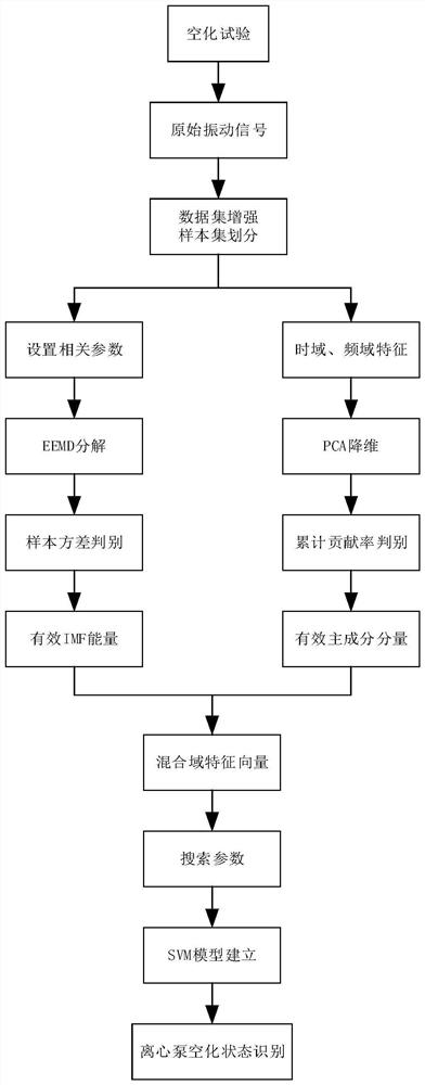
[0044] like figure 1 As shown, the method for identifying the cavitation state of a centrifugal pump of the present invention takes the vibration signals under different cavitation states as the original data, uses the Ensemble Empirical Mode Decomposition (EEMD) to decompose the vibration signals, and calculates the energy of each IMF component. , and calculate the variance value of the energy of the same-order IMF component under different cavitation states, and select the effective IMF energy according to the size of the variance value as the main eigenvector; then extract the time-domain and frequency-domain characteristics of the centrifugal pump vibration signal. Composite eigenvectors, and then use principal component analysis to reduce the dimensionality of the compos...


PUM


Abstract

The invention discloses a centrifugal pump cavitation state identification method, which comprises the following steps of: taking vibration signals in different cavitation states as original data, decomposing the vibration signals by using ensemble empirical mode decomposition, calculating the energy of each IMF component, and calculating the variance value of the energy of the same-order IMF component in different cavitation states; effective IMF energy is selected according to the variance value to serve as a main feature vector; extracting a time domain feature and a frequency domain feature of the centrifugal pump vibration signal to form a composite feature vector, and then performing dimensionality reduction on the composite feature vector to obtain an auxiliary feature vector; and combining the main feature vector and the auxiliary feature vector to construct a mixed domain feature vector, inputting the mixed domain feature vector into a support vector machine for data training and verification, and finally realizing centrifugal pump cavitation state recognition. The method can improve the cavitation recognition accuracy of the centrifugal pump.

Description

technical field [0001] The invention relates to the field of cavitation of centrifugal pumps, in particular to a method for identifying the cavitation state of centrifugal pumps. Background technique [0002] Cavitation is one of the most common failures of centrifugal pumps, also known as cavitation. Cavitation will lead to the reduction of the head, which is easy to cause strong vibration and noise, and at the same time, it will corrode the impeller and affect the service life of the pump. If the cavitation can be monitored and identified in time, the utilization rate and service life of the centrifugal pump can be improved, and the economic cost can be reduced. The vibration signal contains rich state information when the centrifugal pump is running, including the vibration generated by the fluid in the pump during cavitation and the mechanical vibration of the pump itself. Existing cavitation identification technologies mainly include: lift drop method, high-speed phot...

Claims


Application Information

Patent Timeline
IPC IPC(8): G06K9/62G01H17/00
CPCG01H17/00G06F18/2135G06F18/2411G06F18/214
Inventor 周佩剑周陈贵牟介刚徐茂森杨雪龙
Owner CHINA JILIANG UNIV
Learn More