Carbon emission metering method, equipment and carbon metering system

A technology for measuring equipment and carbon emissions, applied in computing, computer parts, data processing applications, etc., can solve problems such as system reliability decline, carbon accounting parameter adjustment, low utilization rate of carbon metering equipment, etc., to improve real-time performance and accuracy, improve system reliability, and save communication costs.

Pending Publication Date: 2022-05-27
阳光慧碳科技有限公司
View PDF0 Cites 0 Cited by
  • Summary
  • Abstract
  • Description
  • Claims
  • Application Information

AI Technical Summary

Problems solved by technology

[0004] The existing technology has the following problems: the underlying metering equipment cannot directly obtain the emission control measurement results, relying on manual methods has a large workload, and does not have practical promotion value in large-scale group enterprises or virtual entities; relying on centralized communication structures to perform carbon accounting requires Centralizing massive amounts of data to the top-level system will easily cause a huge network communication burden, resulting in an increase in the

Method used


Image

  • Carbon emission metering method, equipment and carbon metering system
  • Carbon emission metering method, equipment and carbon metering system
  • Carbon emission metering method, equipment and carbon metering system

Examples


Embodiment 1

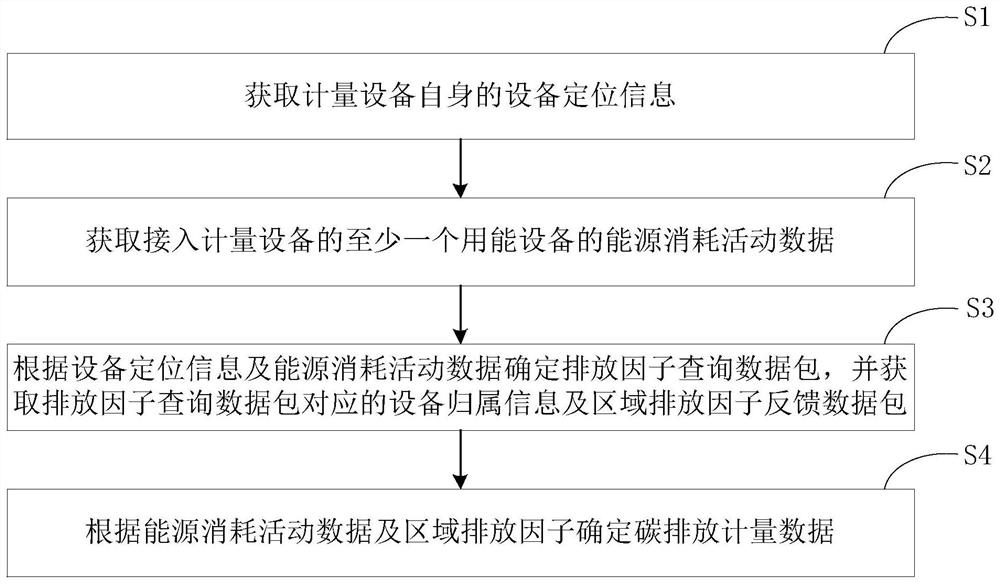
[0028] figure 1 This is a flowchart of a carbon emission measurement method provided in Embodiment 1 of the present invention. This embodiment can be applied to the application scenario of performing distributed emission data aggregation and carbon accounting on the edge measurement device. The edge measurement device can use hardware and / or in the form of software.

[0029] combine figure 1 As shown, the carbon emission measurement method specifically includes the following steps:

[0030] Step S1: Obtain device positioning information of the metering device itself.

[0031] The device positioning information includes but is not limited to information such as longitude, latitude, and altitude of the region where the edge measurement is located.

[0032] Exemplarily, a Global Positioning System (Global Positioning System, GPS) receiver may be used to obtain device positioning information delivered by GPS satellites, and the GPS sends the received device positioning inform...

Embodiment 2

[0087] Image 6 It is a schematic structural diagram of a carbon emission measurement device provided in Embodiment 2 of the present invention. The measurement device is used to execute the above-mentioned carbon emission measurement method, and has functional modules and beneficial effects corresponding to the execution method.

[0088] like Image 6 As shown, the carbon emission metering device 1 includes: a positioning module 101 for acquiring device positioning information of the metering device; a southbound communication module 102 for acquiring energy consumption activity data of at least one energy-consuming device 2; a data processing module 103 , which is used to classify and summarize the energy consumption activity data, and determine the emission factor query data packet according to the equipment positioning information and energy consumption activity data; the northbound communication module 104 is used to send the emission factor query data packet to the contro...

Embodiment 3

[0109] Based on any of the foregoing embodiments, Embodiment 3 of the present invention provides a carbon measurement system, where the system includes the carbon emission measurement device provided in any of the foregoing embodiments, the measurement device is used to execute the above-mentioned carbon emission measurement method, and has an execution method. Corresponding functional modules and beneficial effects.

[0110] Figure 10 It is a schematic structural diagram of a carbon metering system provided in Embodiment 3 of the present invention.

[0111] like Figure 10 As shown, the system 100 includes: an emission control management platform 0 and the above-mentioned carbon emission measurement device 1, the emission control management platform 0 is in communication connection with at least one carbon emission measurement device 1; 1. The uploaded emission factor query data package classifies and summarizes the metering equipment belonging to the same area, and determ...


PUM


Abstract

The invention discloses a carbon emission metering method, equipment and a carbon metering system. The method comprises the following steps: acquiring equipment positioning information of metering equipment; obtaining energy consumption activity data of at least one energy consumption device connected to the metering device; determining an emission factor query data packet according to the equipment positioning information and the energy consumption activity data, and obtaining equipment attribution information corresponding to the emission factor query data packet and a regional emission factor feedback data packet; and determining carbon emission metering data according to the energy consumption activity data and the regional emission factors. According to the invention, the metering equipment determines the equipment attribution information and the emission factors updated in real time in the area where the equipment is located according to the equipment positioning information and the received energy consumption activity data, so that the carbon emission accounting is completed in the distributed metering equipment without depending on fixed equipment types and position conditions, the data real-time performance is improved, and the energy consumption is reduced. Network burden caused by centralized data convergence is avoided, communication cost is saved, and system reliability is improved.

Description

technical field [0001] The invention relates to the technical field of carbon emission accounting, in particular to a carbon emission measurement method, equipment and a carbon measurement system. Background technique [0002] Carbon accounting is based on the boundary of an independent legal entity or an independent accounting unit deemed to be a legal entity, to account and report the greenhouse gas emissions generated by all production sites and production equipment controlled by the operator. [0003] In the existing technology, carbon accounting usually adopts the following two methods: the first method is to manually complete the carbon measurement report and verification of emission control enterprises; the second method is that the accounting system adopts a centralized communication structure and collects emission data through the underlying equipment. , and then centrally summarize the underlying emission data to the enterprise-level monitoring platform and even th...

Claims


Application Information

Patent Timeline
IPC IPC(8): G06Q10/06G06K9/62G06Q50/26
CPCG06Q10/06312G06Q50/26G06Q10/06315G06Q10/0637G06F18/241Y02P90/845
Inventor 苏阳余勇
Owner 阳光慧碳科技有限公司
Why Eureka
Try Eureka