Relay protection circuit based on high-precision zero-cross detection

A relay protection and zero-crossing detection technology, applied in relays, circuits, electrical components, etc., can solve the problems of large error range of the processor signal, misjudgment by the processor, inaccurate detection, etc., to improve the detection accuracy and avoid errors. The effect of judging and avoiding control errors

Pending Publication Date: 2022-05-27
凤凰智能电子(杭州)有限公司
View PDF0 Cites 2 Cited by
  • Summary
  • Abstract
  • Description
  • Claims
  • Application Information

AI Technical Summary

Problems solved by technology

However, the existing zero-crossing detection circuit has the following defects: First, the product circuit structure is simple, such as directly connecting a resistor and an optocoupler in series on the mains, because the range of the current transfer ratio (CTR) of the optocoupler is relatively large, and the optocoupler will increase when the voltage rises. The rate of conduction and cut-off in the process of voltage drop will be different, so that the signal received by the processor has a large error range, resulting in inaccurate detection; second, the output of the optocoupler is usually directly connected to the processor through a resistor. The change signal (such as falling edge) received by the processor will have a relatively large inclination angle, which will easily cause the processor to misjudge

Method used


Image

  • Relay protection circuit based on high-precision zero-cross detection
  • Relay protection circuit based on high-precision zero-cross detection
  • Relay protection circuit based on high-precision zero-cross detection

Examples


Embodiment 1

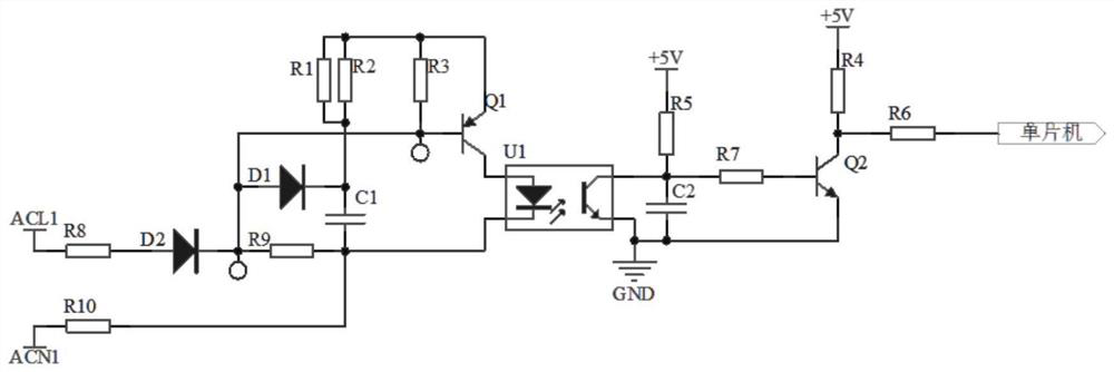
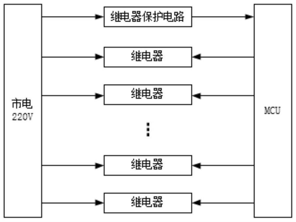
[0031] like Figure 1-3 As shown, a relay protection circuit based on high-precision zero-crossing detection is used to realize the on-off of the relay at the zero point of alternating current. The relay protection circuit based on high-precision zero-crossing detection includes a rectifier circuit, a signal generation circuit, a filter circuit and a Circuits, shaping circuits and processors, wherein:

[0032] A rectifier circuit for converting alternating current into a positive waveform voltage;

[0033] The signal generating circuit includes a first diode D1, a first capacitor C1, a ninth resistor R9, a first transistor Q1 and an optocoupler U1, the rectifier circuit is connected to both ends of the ninth resistor R9, and the first diode D1 The positive electrode and the first electrode of the first transistor Q1 are respectively connected to one end of the ninth resistor R9, one end of the first capacitor C1 and the cathode of the optocoupler U1 are respectively connected...

Embodiment 2

[0055] like Figure 4-5 As shown, a relay protection circuit based on high-precision zero-crossing detection is based on Embodiment 1. The difference is that: in this embodiment, the rectifier circuit includes a rectifier bridge DB1, and the first input terminal AC1 of the rectifier bridge DB1 is connected to the power live wire ACL1 , the second input terminal AC2 is connected to the power neutral line ACN1, the first output terminal V+ is connected to the anode of the first diode D1, and the second output terminal V- is connected to the cathode of the optocoupler U1.

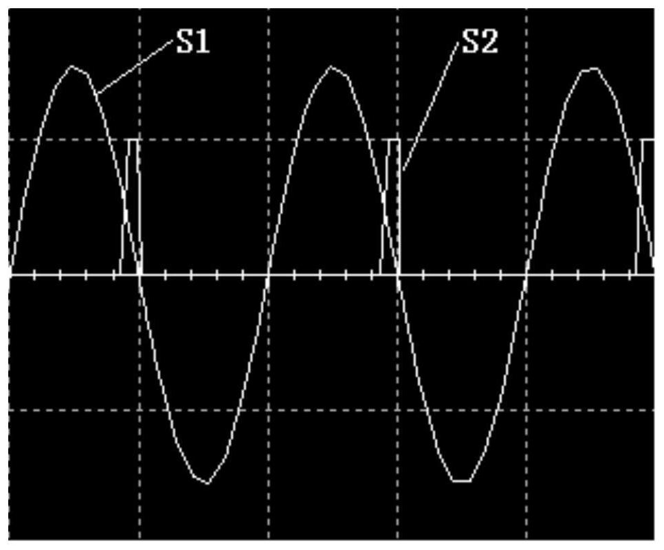
[0056] Among them, the alternating current (such as commercial power 220V) is rectified by the rectifier bridge DB1, and the negative half-cycle waveform is also rectified into a positive half-wave, and is connected from the first output terminal V+ (positive output terminal) of the rectifier DB1 to the first transistor Q1 all the way. The first pole, the other way limits the voltage drop across the optocouple...


PUM


Abstract

The invention discloses a relay protection circuit based on high-precision zero-cross detection, which comprises a rectification circuit, a signal generation circuit, a filter circuit, a shaping circuit and a processor which are electrically connected in sequence, and is characterized in that the rectification circuit is used for converting alternating current into positive waveform voltage; the signal generation circuit comprises a first diode, a first capacitor, a ninth resistor, a first transistor and an optocoupler, and the on-off of the optocoupler is realized by controlling the on-off of the first transistor; the processor is connected with at least one relay and is used for receiving the output signal and recording the action times of the relay, receiving the first output signal when the optocoupler is switched off, receiving the second output signal when the optocoupler is switched on, and judging an alternating current zero point when detecting that the second output signal is changed into the first output signal; the relay is controlled to be switched on and off at an alternating current zero point. The device can realize accurate on-off of the relay at an alternating current zero point, can simultaneously control a plurality of relays to act, and is long in service life, high in precision, small in size, low in cost, stable and reliable.

Description

technical field [0001] The invention belongs to the technical field of relay protection, in particular to a relay protection circuit based on high-precision zero-crossing detection. Background technique [0002] With the continuous improvement of the level of industrialization, the number of intelligent household appliances is increasing, and it is more and more inseparable from the control of relays. For example, for a long time, the heating system of kitchen appliances has often used relays to control the heating components, but because the kitchen appliances are powered by the mains, the relay contacts are often damaged due to ignition and arcing, which makes the relay invalid and the product cannot be used, which seriously affects Reliability and service life of kitchen appliances. [0003] Most of the current relays are by adding a zero-crossing detection circuit. By detecting the zero-crossing point, the relay is turned on at the zero-crossing point to avoid the rela...

Claims


Application Information

Patent Timeline
Patent Type & Authority Applications(China)
IPC IPC(8): H01H47/02H01H47/00
CPCH01H47/02H01H47/002
Inventor 孙茂植赵江李刚祥葛群虎严朝磊
Owner 凤凰智能电子(杭州)有限公司
Why Eureka
Try Eureka