Live-line work robot lead lap joint device and lap joint method

A technology of lead wire lapping and live work, which is applied to the installation of cables, busbars, manipulators, etc., can solve the problems of high labor intensity, high processing difficulty, personal danger of live work personnel, etc., and achieve design and component simplification, Reduced power and weight, increased ease of disengagement

Pending Publication Date: 2022-05-27
福建大观电子科技有限公司
View PDF1 Cites 0 Cited by
  • Summary
  • Abstract
  • Description
  • Claims
  • Application Information

AI Technical Summary

Problems solved by technology

[0003] At present, the 10kV power distribution line operation site widely adopts the intermediate potential operation method of the insulated bucket arm truck. The operator uses the original tool to manually complete the live work task, and the operator needs to perform wiring and untwisting in extremely dangerous environments such as high altitude, high voltage, and strong electromagnetic field. Manual operation is labor-intensive and highly stressful, which not only brings personal danger to live workers, but also reduces work efficiency
[0004] Chinese invention patent ZL202111132366.0 discloses a lead wire lapping device and a wire clamp installation method for a live working robot. The lead wire lapping device of this patent document has the following disadvantages: 1. The torque (torque) adjustable sleeve has a complex structure and is difficult to process High, high cost; 2. The torque (torque) adjustable sleeve structure requires high deviation accuracy of the clamping position of the wire clamp

Method used


Image

  • Live-line work robot lead lap joint device and lap joint method
  • Live-line work robot lead lap joint device and lap joint method
  • Live-line work robot lead lap joint device and lap joint method

Examples


Embodiment Construction

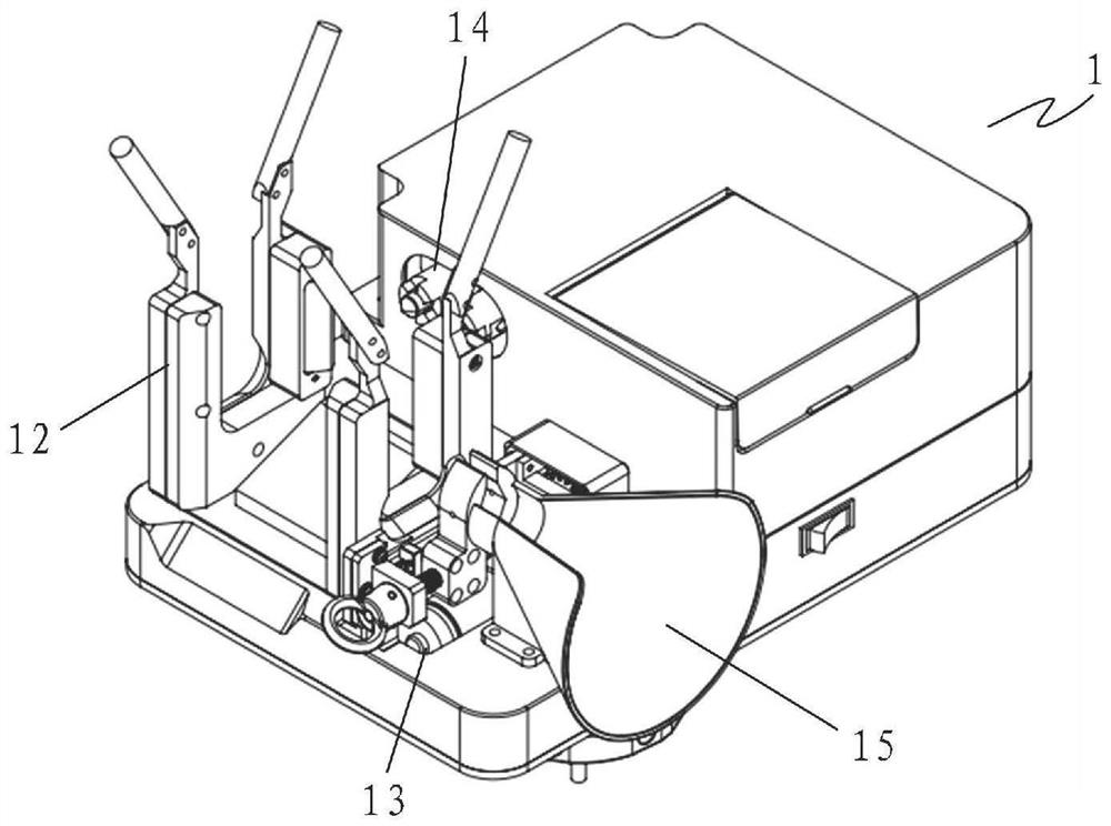
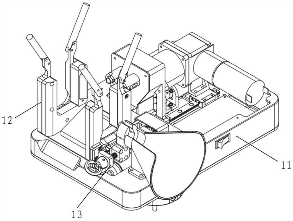
[0067] see Figure 1 to Figure 10 As shown, a lead wire bonding device of a live working robot includes: a wiring tool 1 and a wire clip 2;

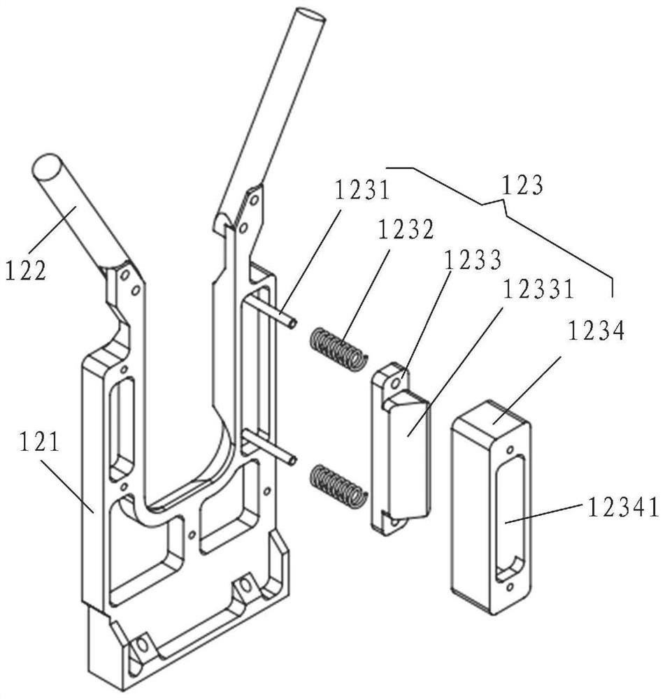
[0068] The wiring tool 1 includes: a frame 11 , a wire clamp mounting mechanism 12 , a lead wire clamping mechanism 13 and a wire clamp tightening mechanism 14 ; the wire clamp installation mechanism 12 and the wire clamp mechanism 12 are arranged side by side at the front end above the frame 11 , the wire clamp tightening mechanism 14 is arranged at the rear end above the frame 11;

[0069] like Figure 4 As shown, the wire clip 2 includes: a front side part 21 and a rear side part 22. The front side part 21 and the rear side part 22 are connected by at least a pair of bolts, and the front side part 21 and the rear side part 22 are connected by at least one pair of bolts. A busbar slot 23 and a lead slot 24 are formed between the busbars and the lead wires; a wire clip fixing box, the wire clip is installed in the wire clip fixing box...


PUM


Abstract

The invention discloses a hot-line work robot lead lap joint device and method. The device comprises a wiring tool and a wire clamp. The wiring tool comprises a rack, a wire clamp mounting mechanism, a lead clamping mechanism and a wire clamp tightening mechanism, the wire clamp mounting mechanism and the lead wire clamping mechanism are arranged at the front end above the rack side by side, and the wire clamp tightening mechanism is arranged at the rear end above the rack; the wire clamp comprises a front side part and a rear side part, the front side part and the rear side part are connected through at least one pair of bolts, and a bus groove and a lead groove for a bus and a lead to pass through are formed between the front side part and the rear side part; the wire clamp mounting mechanism is used for clamping a wire clamp; the lead enters the lead groove of the wire clamp from the lead guide groove and then is clamped by the lead clamping mechanism; the wire clamp tightening mechanism comprises two screwdriver head assembly units and a screwdriver head driving unit, wherein the two screwdriver head assembly units are designed side by side. According to the invention, the wire clamp nut can be uniaxially and asynchronously screwed, the wiring tool and the wire clamp can be automatically separated after screwing, and the power consumption is low.

Description

technical field [0001] The invention belongs to the technical field of a live working robot device, and particularly relates to a lead wire overlapping device and a lapping method of a live working robot. Background technique [0002] With the rapid development of my country's economy and power grid construction, economic construction and people's lives are increasingly dependent on electricity, and society's ability to withstand power outages is getting worse and worse. Live work is one of the important means to solve this problem. Live work refers to the testing and maintenance of high-voltage electrical equipment under the condition of uninterrupted power supply. It is an effective operation to avoid power failure during maintenance and ensure normal power supply. method. The 10kV distribution network is located at the end of the power system and is a key link to ensure continuous power supply. Its reliability occupies a very important position in the entire power supply...

Claims


Application Information

Patent Timeline
IPC IPC(8): H02G1/14H02G1/02H02G5/00B25J11/00B25B27/14
CPCH02G1/14H02G1/02H02G5/00B25J11/00B25B27/143
Inventor 王涛王国斌陈兵纪雄斌
Owner 福建大观电子科技有限公司
Why Eureka
Try Eureka