Part oiling machine

A technology of oiling machine and parts, which is applied in the field of parts processing, can solve the problems of oil stains and other problems, achieve high stability, simple and easy structure, and increase the effect of structural complexity

Pending Publication Date: 2022-05-31
CHONGQING YUJIANG DIE CASTING
View PDF1 Cites 0 Cited by
  • Summary
  • Abstract
  • Description
  • Claims
  • Application Information

AI Technical Summary

Problems solved by technology

[0005] The object of the present invention is to provide a part oiling machine to solve the problem in the prior art that oil stains are easily formed on the non-oiled parts of the parts when oiling the parts to be oiled.

Method used


Image

  • Part oiling machine
  • Part oiling machine
  • Part oiling machine

Examples


Embodiment Construction

[0040] The following is further described in detail by specific embodiments:

[0041] Reference numerals in the drawings in the description include:

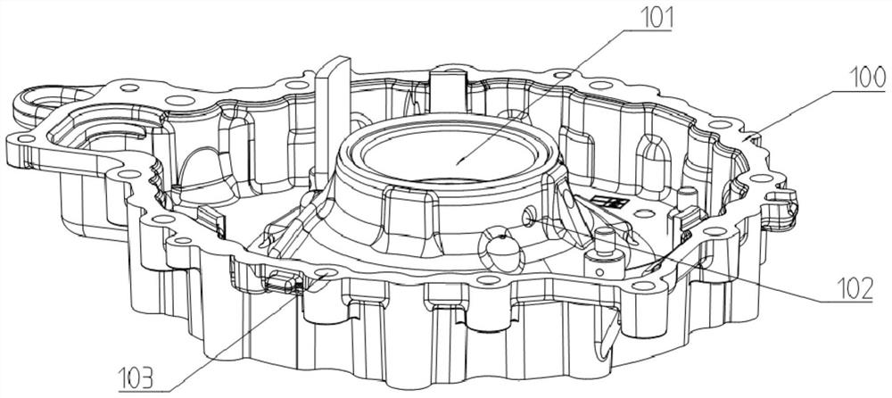
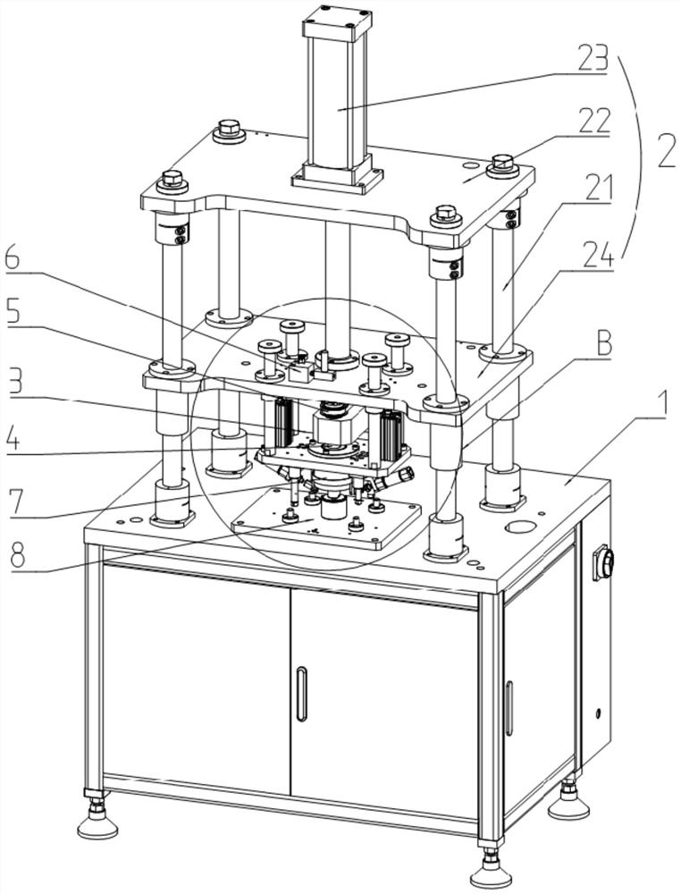
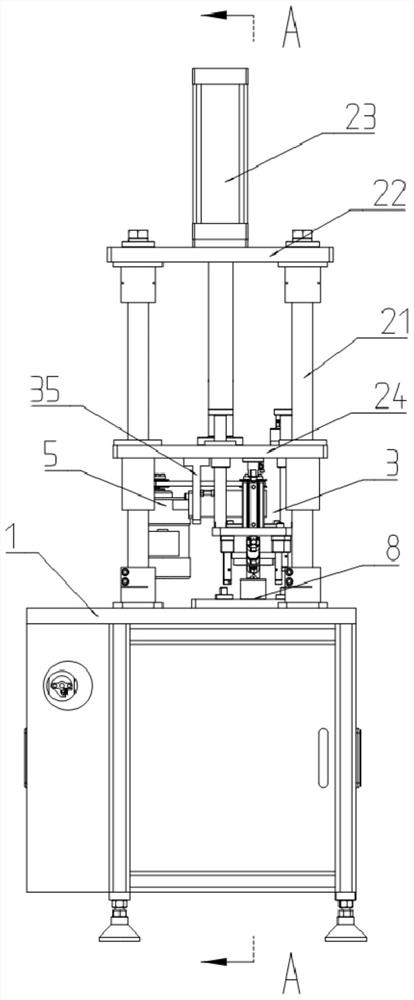
[0042] Parts 100, oiling holes 101, side holes 102, positioning holes 103, frame 1, total drive mechanism 2, column 21, top plate 22, total drive cylinder 23, mounting plate 24, floating pressing part 3, connecting plate 31, Single-acting cylinder 32, guide column 33, limit block 34, support plate 35, transmission hole 351, fuel injection rod 4, oil passage 42, fuel injection hole 43, rotary joint 44, bearing seat 45, bearing 46, rotating device 5 , motor 51, driving wheel 52, belt 53, driven wheel 54, oil supply assembly 6, oil drum 61, oil inlet pipe 62, throttle valve 63, gas-liquid two-phase atomizer 64, oil outlet pipe 65, pressing seat 7 , the first sealing ring 71, the pressure rod 72, the plug 73, the tubular cylinder 74, the working hole 76, the placing seat 8, the blocking column 81, the second sealing ring 82, the po...


PUM


Abstract

The invention relates to the technical field of part machining, and particularly discloses a part oiling machine which comprises a rack, a driving assembly and a containing base used for containing parts are installed on the rack, and the driving assembly is located above the containing base; the driving assembly comprises a main driving mechanism and a floating pressing part, and the floating pressing part is connected to the output end of the main driving mechanism; an oil injection rod and a rotating device used for driving the oil injection rod to rotate are installed at the output end of the main driving mechanism, the oil injection rod communicates with an oil supply assembly, and the oil injection rod is vertically connected to the floating pressing part in a sliding mode. And sealing rings are arranged on the lower end surface of the floating pressing part and the upper end surface of the placing seat. By adopting the technical scheme provided by the invention, the problem that oil stains are easy to form on non-oil-coated parts of the part when oil is coated on the to-be-oil-coated part of the part in the prior art can be solved. The scheme is mainly used for oiling the hole wall of the part.

Description

technical field [0001] The invention relates to the technical field of parts processing, in particular to a part oiling machine. Background technique [0002] When manufacturing parts with holes, the hole walls of the parts need to be oiled during processing to prevent them from rusting during use and affect the service life of the parts. The existing oiling method for parts is manually applied, but manual application is not only inefficient, but also prone to uneven application, resulting in uneven oiling on the hole wall of the part, and inconsistent antirust effect on the hole wall of the part ; In addition, manual smearing cannot accurately control the amount of oil applied, and excess oil flowing to non-hole walls will form oil stains, which will affect the appearance of the parts. [0003] In response to the above problems, the invention patent with the authorized notification number CN110538753B proposes an automatic oiling device for the inner edge of the workpiece,...

Claims


Application Information

Patent Timeline
Patent Type & Authority Applications(China)
IPC IPC(8): B05B13/06B05B12/20
CPCB05B13/06B05B13/0636B05B12/20Y02P70/10
Inventor 陈松
Owner CHONGQING YUJIANG DIE CASTING
Why Eureka
Try Eureka