
Control device and method for assembling sectors of turbine stator of turbine

A technology of a control device and a control method, applied in the fields of aero-engines and turbines, can solve problems such as quality loss and error sources, and achieve the effects of improving efficiency and profitability, being easy to reproduce, and ensuring quality.

Pending Publication Date: 2022-05-31
SAFRAN AIRCRAFT EGINES
View PDF2 Cites 0 Cited by
  • Summary
  • Abstract
  • Description
  • Claims
  • Application Information

AI Technical Summary

Problems solved by technology

These repetitive operations can also be a source of errors and thus cause a loss of mass in the final assembly of the turbine stator

Method used


Image

  • Control device and method for assembling sectors of turbine stator of turbine
  • Control device and method for assembling sectors of turbine stator of turbine
  • Control device and method for assembling sectors of turbine stator of turbine

Examples


Embodiment Construction

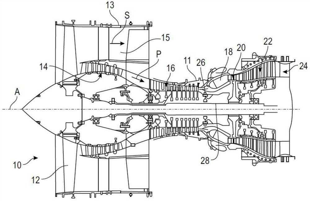
[0068] figure 1 A turbomachine 10 of the twin-flow type with a longitudinal axis A is shown. Such a turbine 10 (here a turbojet 10 ) includes a fan 12 , a low pressure (LP) compressor 14 , a high pressure (HP) compressor 16 , a combustor 18 , a high pressure (HP) turbine 20 , a low pressure (LP) compressor 16 in a known manner LP) turbine 22 and exhaust nozzle 24 . The rotor of the HP compressor 16 and the rotor of the HP turbine 20 are connected by the high pressure HP shaft 26 and form a high pressure body with the high pressure HP shaft 26 . The rotor of the LP compressor 14 and the rotor of the low pressure LP turbine 22 are connected by the LP shaft 28 and form a low pressure body with the LP shaft 28 .

[0069] The primary air flow "P" passes through the high and low pressure bodies, and the fan 12 produces a secondary air flow "S" in the cold flow passage 15, which is The casing 11 and the outer casing 13 communicate with each other. At the outlet of the nozzle 24, ...


PUM


Abstract

The invention relates to a control device and a method for assembling sectors of a turbine stator of a turbine, a control device (120) for assembling sectors of a turbine stator (32) of a turbine (22), each turbine stator being formed from an assembly of sectors (34) juxtaposed to one another, each sector comprising an identification, the device comprising: an automation system (122) for identifying sectors, the automation system comprises means for reading sector identifications; a database of identifications intended to form sectors of a turbine stator of the turbine; and means for associating the read sector identification with a determined turbine stator of the turbine.

Description

technical field [0001] The field of the invention is that of aero-engines, especially turbines. [0002] In particular, the present invention relates to an apparatus and method for assembling a turbine stator of a turbine turbine. Background technique [0003] Aviation turbines typically include multiple modules, such as a low pressure (LP) compressor, then a high pressure (HP) compressor, a combustor, a high pressure turbine, then a low pressure turbine (which drive the corresponding LP or HP compressor), and for injection gas system. [0004] Each turbine of such a machine typically includes a plurality of stages, each stage including an annular row or ring of stationary vanes supported by the casing of the turbine and an annular row of vanes rotatably mounted about a central axis of rotation. The stationary inner blade ring of the turbine is also called the turbine stator. [0005] In order to facilitate their assembly and reduce their manufacturing costs, stationary b...

Claims


Application Information

Patent Timeline
IPC IPC(8): F01D25/28F01D9/04
CPCF01D25/28F01D9/042F01D9/041F05D2230/60F01D9/04F01D25/246F05D2230/68F05D2260/30F05D2230/50F05D2230/51Y02T50/60F01D11/122F01D25/24F05D2240/14F05D2250/283G06T7/001G06T2207/30164
Inventor 昂盖郎·弗雷德里克·德阿戈斯蒂尼卡洛斯·阿尔维斯·德马托斯佛罗莱恩·肖韦尔巴普蒂斯特·伊帕维耶马赛厄斯·加格力亚朵艾伯纳·维斯第
Owner SAFRAN AIRCRAFT EGINES
Learn More