
Hemispherical resonator gyroscope based on optical cement connection mode

A technology of hemispherical resonant gyroscope and connection method, which is applied in the direction of speed measurement by gyro effect, gyroscope/steering sensing equipment, instruments, etc., which can solve the problems of complex adjustment mechanism, loss of adjustment accuracy, and influence on installation and adjustment accuracy, and meet the requirements of the process. required effect

Active Publication Date: 2022-05-31
HUAZHONG PHOTOELECTRIC TECH INST (CHINA SHIPBUILDING IND CORP THE NO 717 INST)
View PDF6 Cites 1 Cited by
  • Summary
  • Abstract
  • Description
  • Claims
  • Application Information

AI Technical Summary

Problems solved by technology

[0004] At present, the structure and assembly methods of the hemispherical resonator gyroscope in the relevant literature have the following deficiencies: First, a high-precision displacement mechanism is used to adjust the relative position of the resonator and the electrode holder, so as to ensure the strict positional relationship between the two. This causes the adjustment mechanism to be more complicated, and part of the adjustment accuracy will be lost in the subsequent brazing or other fixing methods; the second is to use brazing or bonding to fix the resonator and the electrode holder, both of which require a higher This will cause thermal deformation of the resonator, electrode holder and fixture, which will affect the final assembly accuracy

Method used


Image

  • Hemispherical resonator gyroscope based on optical cement connection mode
  • Hemispherical resonator gyroscope based on optical cement connection mode
  • Hemispherical resonator gyroscope based on optical cement connection mode

Examples


Embodiment Construction

[0032] In order to facilitate the understanding of the present application, the present application will be described more fully below with reference to the relevant drawings. Embodiments of the application are given in the drawings. However, the present application can be embodied in many different forms and is not limited to the embodiments described herein. On the contrary, the purpose of providing these embodiments is to make the disclosure of this application more thorough and comprehensive.

[0033] Unless otherwise defined, all technical and scientific terms used herein have the same meaning as commonly understood by one of ordinary skill in the technical field to which this application belongs. The terms used herein in the specification of the application are only for the purpose of describing specific embodiments, and are not intended to limit the application.

[0034] It will be appreciated that spatially relative terms such as "under", "beneath", "below", "under",...


PUM

PropertyMeasurementUnit
Parallelismaaaaaaaaaa

Abstract

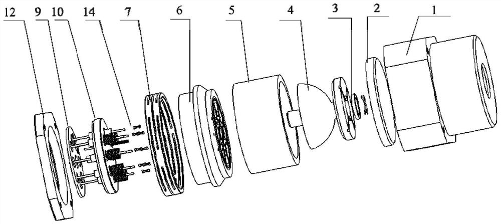
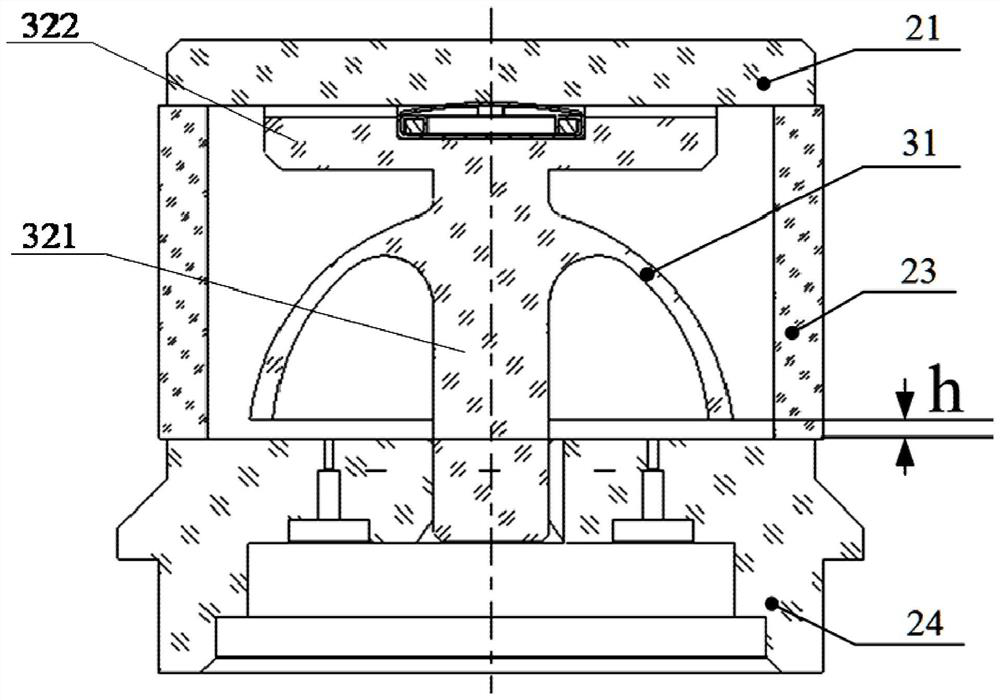
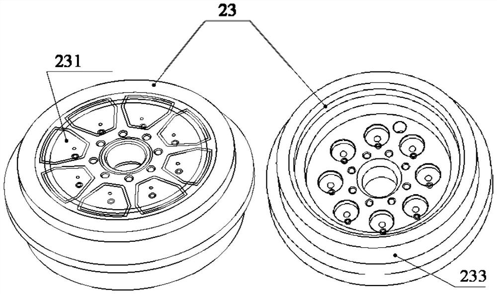
The invention relates to a hemispherical resonator gyroscope based on an optical cement connection mode. The hemispherical resonator gyroscope comprises an outer cover, an optical cement fixing assembly, a harmonic oscillator, a getter and a vacuum communicating vessel, one end of the outer cover is opened and is internally provided with a cavity; the optical cement fixing assembly comprises an optical cement substrate, a supporting ring and an electrode holder, the optical cement substrate is installed at the bottom of the cavity, the electrode holder is arranged at the end, close to the opening of the outer cover, of the cavity, the supporting ring is installed between the optical cement substrate and the electrode holder, and the two ends of the supporting ring are in optical cement connection with the optical cement substrate and the electrode holder respectively; the harmonic oscillator comprises a hemispherical part and a supporting rod, one end, close to an opening of the hemispherical part, of the supporting rod is mounted on the electrode holder, and the other end is in optical cement connection with the optical cement substrate; the getter is mounted at one end, deviating from the opening of the hemispherical part, of the supporting rod; the vacuum communicating vessel is mounted on one side, far away from the optical cement substrate, of the electrode holder; the optical cement mode is adopted for connection so that dimensional tolerance can be strictly controlled, and it is guaranteed that the process requirement is met after installation and adjustment.

Description

technical field [0001] The invention relates to the technical field of hemispherical resonant gyroscopes, in particular to a hemispherical resonant gyroscope based on optical glue connection. Background technique [0002] Hemispherical resonant gyroscope (HRG) is a kind of vibrating gyroscope without high-speed rotor and movable support, which has the characteristics of high precision, small mass, small volume, short start-up time, high overload and high reliability. Known as the most potential Gothic vibrating top. The working principle of HRG is based on the Coriolis effect produced when the hemispherical shell harmonic oscillator rotates around the central axis, so that its mode shape precesses relative to the shell in the ring direction. [0003] The currently developed hemispherical resonator gyro generally adopts a "two-piece" structure, and the main parts include a resonator and an electrode seat. Among them, the electrode seat adopts a flat or spherical structure, ...

Claims


Application Information

Patent Timeline
IPC IPC(8): G01C19/5691G01C19/5783
CPCG01C19/5691G01C19/5783Y02D30/70
Inventor 王鹏曲天良车驰骋张熙刘天怡张红波
Owner HUAZHONG PHOTOELECTRIC TECH INST (CHINA SHIPBUILDING IND CORP THE NO 717 INST)
Learn More