Omnibearing detection mechanical arm of mining robot

A technology of manipulators and robots, which is applied in the field of all-round detection manipulators for mining robots, can solve problems such as narrow corners and inaccessibility of mining robots, and achieve the effect of improving work efficiency and ensuring mine safety

Pending Publication Date: 2022-06-03
王之健
View PDF0 Cites 0 Cited by
  • Summary
  • Abstract
  • Description
  • Claims
  • Application Information

AI Technical Summary

Problems solved by technology

[0005] The technical problem to be solved by the present invention is: when an accident occurs in a mine, a mining robot is required to detect the situation in the mine first, so as to facilitate the entry of subsequent technicians. As a result, mining robots cannot reach this problem

Method used


Image

  • Omnibearing detection mechanical arm of mining robot
  • Omnibearing detection mechanical arm of mining robot
  • Omnibearing detection mechanical arm of mining robot

Examples


specific Embodiment approach

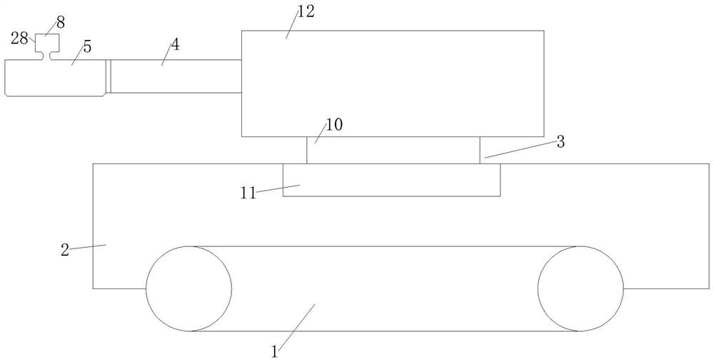
[0066] As a specific embodiment of the present invention, the rotating assembly 3 further includes:

[0067] a rotating shaft 10, the rotating shaft 10 is located above the vehicle frame 2 and is rotatably connected with the vehicle frame 2;

[0068] No. 1 motor 11, the output shaft of the No. 1 motor 11 is fixedly connected to the rotating shaft 10;

[0069] a base 12, the base 12 is located above the rotating shaft 10 and is fixedly connected with the rotating shaft 10;

[0070] When the No. 1 motor 11 is started, it drives the rotating shaft 10 fixedly connected to the output shaft of the No. 1 motor 11 to also rotate, thereby driving the base 12 fixedly connected to the other end of the rotating shaft 10 to also rotate, so that the base 12 fixedly connected to the base 12 also rotates. The manipulator support 4 also rotates following the base 12, so that the detection manipulator 5 connected to the manipulator support 4 can detect the surrounding environment.

[0071] As...

Embodiment approach

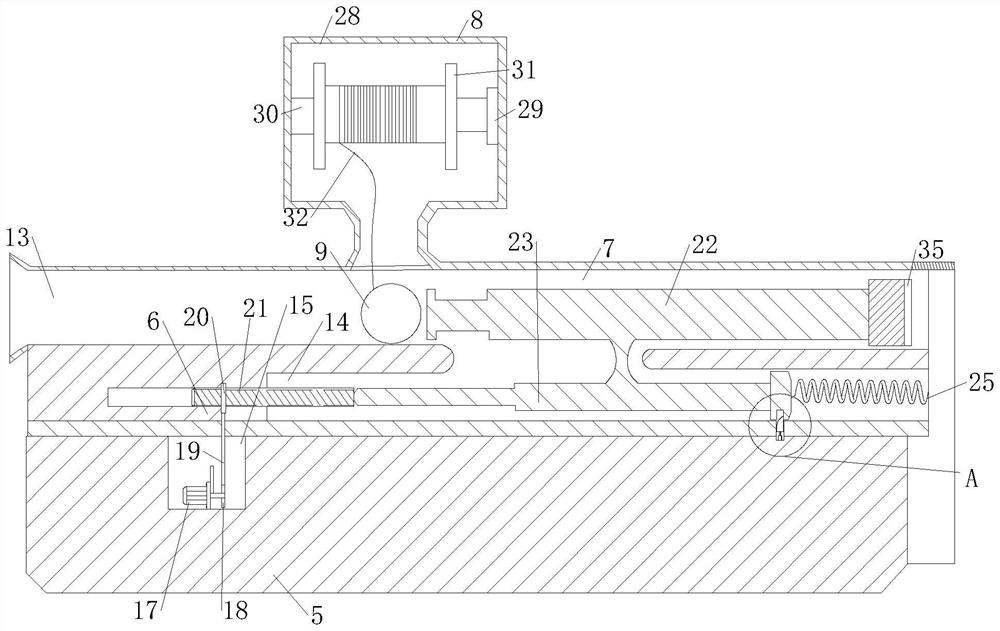
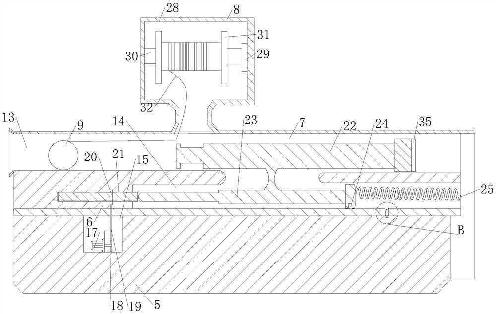
[0096] As a specific embodiment of the present invention, an annular flexible rubber 34 is fixedly connected to the outer surface of the detection ball 9 .

[0097] In order to prevent the detection ball 9 from being broken when it is launched and landed, a ring-shaped flexible rubber 34 is provided on the surface of the detection ball 9. The flexible rubber 34 surrounds the detection ball 9 and has holes at the position of the detection element 33 to prevent the detection element from being blocked. 33 line of sight, while protecting the detection ball 9.

[0098] As a specific embodiment of the present invention, the flexible wire 32 is made of ultra-high molecular weight polyethylene fiber material.

[0099] The ultra-high molecular weight polyethylene fiber material has good wear resistance, weather resistance and corrosion resistance and flexibility.

[0100] As a specific embodiment of the present invention, a flexible rubber 35 is provided at one end of the No. 2 rod 2...


PUM


Abstract

The invention relates to the field of mining robots, in particular to an omni-directional detection mechanical arm of a mining robot. Comprising crawler-type wheels and a frame, and further comprises a rotating assembly located above the frame; the detection mechanical arm is located at the end, away from the rotating assembly, of the mechanical arm supporting column; the force storage assembly is located in the detection mechanical arm; the launching assembly is located on the side, close to the mechanical arm supporting column, of the force storage assembly, and the recovery assembly is located above the detection mechanical arm and connected with the detection mechanical arm; according to the device, the detection mechanical arm, the rotating assembly, the force storage assembly, the transmitting assembly, the recovery assembly and the like are arranged, so that places with problems of water permeation, poor road conditions, narrow corners and the like are detected, technical personnel can obtain timely data, and the detection efficiency is improved. And the mine safety is ensured.

Description

technical field [0001] The invention relates to the field of mining robots, in particular to an omnidirectional detection mechanical arm of a mining robot. Background technique [0002] The mining detection robot is a robot that can transmit various information collected to the main control center in the form of images and data to complete the underground operation, so that the personnel can timely understand the situation in the mine. It has a variety of detection functions and can detect various Various environmental parameters, such as the concentration of various harmful gases in the well, the temperature and humidity of the environment, the location and status of personnel or equipment, etc., facilitate the normal work of the staff and ensure the personal safety of the staff. [0003] At present, the mining detection robots on the market mainly collect various environmental parameters in the well, and can replace the technical personnel for detection. However, for the ...

Claims


Application Information

Patent Timeline
IPC IPC(8): B25J5/00B25J11/00G01D21/02
CPCB25J5/005B25J11/00G01D21/02
Inventor 王之健陈忠毅徐文强
Owner 王之健
Why Eureka
Try Eureka