Independent operation bottom thread mechanism of separation type lockstitch sewing machine

An independent operation, lockstitch sewing machine technology, applied in the sewing machine thread cutting mechanism, sewing machine collar mechanism, sewing machine thread take-up device, etc., can solve the problems of high transmission efficiency, low manufacturing difficulty, complex mechanical transmission structure, etc. Achieve the effect of improving transmission efficiency, simplifying mechanical structure and strong versatility

Pending Publication Date: 2022-06-03
QIXING INTELLIGENT TECH CO LTD
View PDF0 Cites 0 Cited by
  • Summary
  • Abstract
  • Description
  • Claims
  • Application Information

AI Technical Summary

Problems solved by technology

[0004] Aiming at the problem of complex mechanical transmission structure in existing locket sewing machines, the application provides a separate locket sewing machine with high transmission efficiency and low manufacturing difficulty, which has an upper thread mechanism, a bottom thread mechanism and a platen, and is characterized in that the bottom thread The mechanism is connected to the main shaft motor of the upper thread mechanism without mechanical transmission. The bottom thread mechanism has a cloth feeding dog assembly, a rotary hook assembly and a thread trimmer assembly installed in a fixed seat, and the fixed seat is installed under the table. The upper thread The mechanism has a thread take-up assembly, and the thread take-up assembly has a thread take-up disc at an eccentric position and is fixed with a take-up column. The upper thread mechanism has a presser foot assembly and a thread take-up assembly. Components and Cutting Components

Method used


Image

  • Independent operation bottom thread mechanism of separation type lockstitch sewing machine
  • Independent operation bottom thread mechanism of separation type lockstitch sewing machine
  • Independent operation bottom thread mechanism of separation type lockstitch sewing machine

Examples


Embodiment Construction

Detailed ways

[0030] The preferred embodiments of the present application will be described in detail below in conjunction with the accompanying drawings, so that the advantages and features of the present application can be more easily understood by those skilled in the art, so that the protection scope of the present application can be more clearly defined. These embodiments It is only used to illustrate the present invention, but not to limit the present invention.

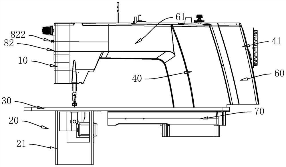
[0031] figure 1Shown is a schematic structural diagram of an independent running bottom thread mechanism of a separate lockstitch sewing machine of the present application. The structure of the lockstitch machine of the present application has a head 40, a controller 60, a platen 30 and a base 70. The above-mentioned machine head 40 has an on-line mechanism 10, a spindle motor 41 and a controller 60. The operation panel 61 of the controller 60 is installed on the front of the machine head 40, the controller ...


PUM


Abstract

The invention relates to an independent operation bottom thread mechanism of a separation type lockstitch sewing machine, provides a sewing machine for sewing through cooperative rotation of an upper thread mechanism and the bottom thread mechanism, and particularly relates to the technical field of sewing machine manufacturing. The sewing machine is provided with an upper thread mechanism, a bottom thread mechanism and a needle plate, the upper thread mechanism and the bottom thread mechanism rotate cooperatively with a machine needle as a center shaft for sewing, and a fixing seat of the bottom thread mechanism is connected with the needle plate. The thread feeding mechanism is fixedly installed on an output shaft of the thread feeding driving motor, the thread feeding driving motor rotates with the machine needle as the center shaft, the bottom thread mechanism is installed on an output shaft of the bottom thread driving motor, and the bottom thread driving motor rotates with the machine needle as the center shaft. According to the rotary intelligent sewing machine, the upper thread mechanism and the bottom thread mechanism are ingeniously separated in structure and power, sewing of special stitches of the sewing machine is effective, the rotary intelligent sewing machine can be applied to sewing of different sewing products, the special sewing function can also be applied to different sewing machines, high practicability is achieved, and the rotary intelligent sewing machine is suitable for large-scale popularization and application. And the market prospect is wide.

Description

technical field [0001] The present application proposes an independent running bottom thread mechanism of a separable lockstitch machine, and specifically relates to the technical field of lockstitch machine manufacturing. Background technique [0002] Lockstitch machine is a sewing equipment for sewing garments, bags, shoes and hats, and quilts. In a traditional lockstitch machine, the main shaft motor is connected to the upper main shaft, and the main shaft motor drives the upper main shaft to rotate, thereby driving the eccentric rotating wheel, the bevel gear and the needle bar crankshaft fixed to the upper main shaft to run at the same time. In the bottom thread sewing transmission mechanism, the eccentric rotating wheel drives the feed link and the lift link at the same time, the feed link drives the feed shaft through the swing seat assembly, and the lift link drives the lift shaft through the lift crank. Swing; the swing of the feeding shaft drives the tooth frame f...

Claims


Application Information

Patent Timeline
Patent Type & Authority Applications(China)
IPC IPC(8): D05B49/04D05B27/02D05B29/02D05B65/00D05B57/14D05B57/26
CPCD05B49/04D05B27/02D05B65/00D05B29/02D05B57/14D05B57/26
Inventor 林子春潘林勇刘冰陈通平刘霖吴文俊李质彬林群
Owner QIXING INTELLIGENT TECH CO LTD
Why Eureka
Try Eureka