[0019] The present invention will be further described in detail below with reference to the accompanying drawings and specific embodiments.
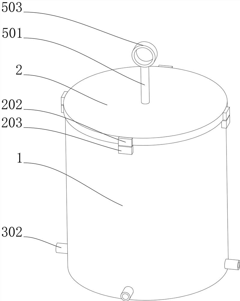
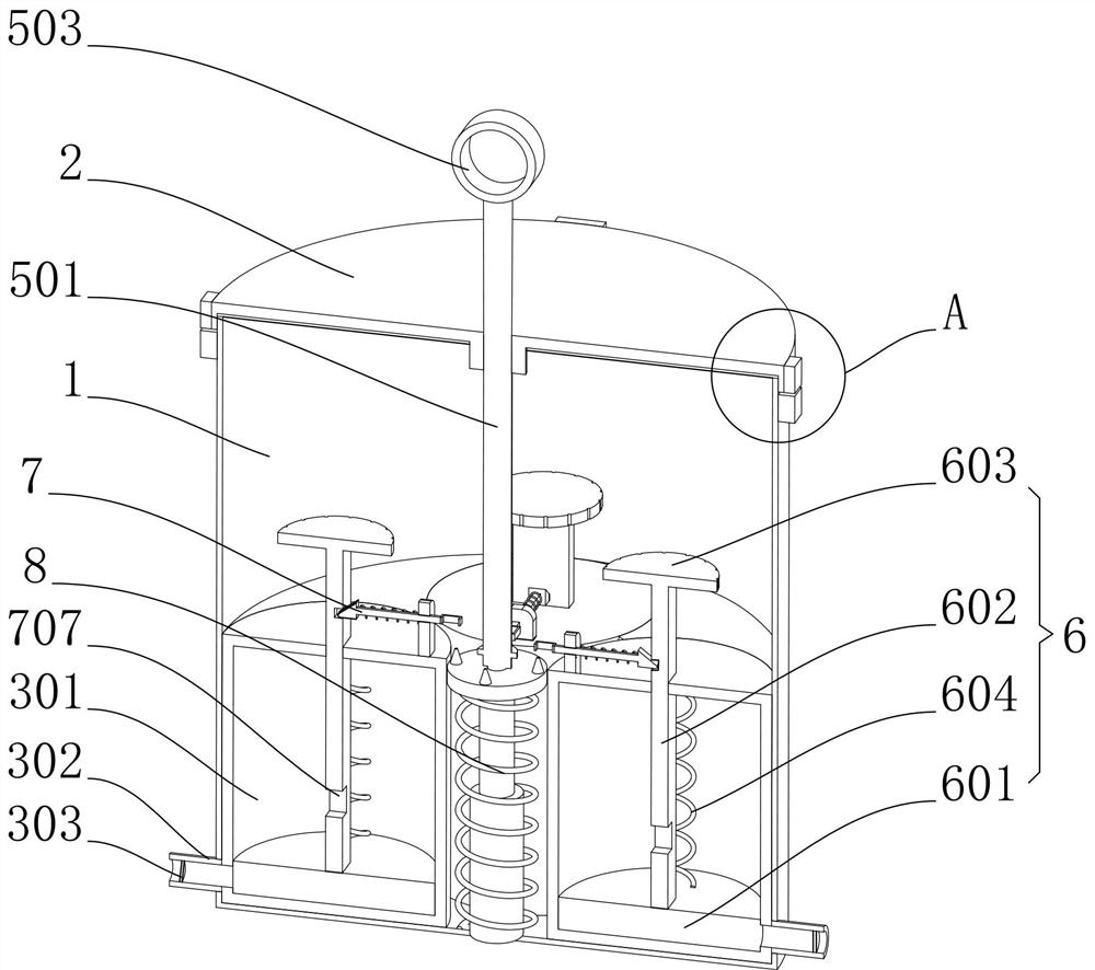
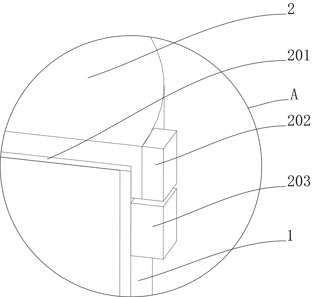
[0020] like Figure 1-8 Shown: an energy-saving and environmentally friendly portable water environment sampling device, comprising a box body 1, a box cover 2 and a sampler 3 for water storage, the sampler 3 is arranged inside the box body 1, and the sampler 3 The number is multiple, and the box cover 2 is provided with a connection assembly 5 that is fixedly connected with the wire rope; the sampler 3 is internally provided with an energy storage assembly 6 for water absorption, and the upper surface of the sampler 3 is provided with a limit The limit assemblies 7 of the energy storage assembly 6 are movable, and the limit assemblies 7 corresponding to each sampler 3 are of different heights. The inner bottom wall of the box body 1 is provided with a control assembly 8 to control the movement of the limit assemblies 7 .
[0021] Preferably, a gap is formed between two adjacent samplers 3 , and the gap is filled with a counterweight 4 .
[0022] Preferably, a gasket 201 is fixedly connected to the inner top wall of the box cover 2 , a plurality of lock buckles 202 are installed on the outer surface of the box cover 2 , and lock buckles 202 are installed on the outer surface of the box body 1 . Fitted lock body 203 . , the box cover 2 is installed through the cooperation of the lock buckle 202 and the lock body 203, and the sealing gasket 201 improves the sealing between the box cover 2 and the box body 1;
Preferably, the sampler 3 includes a water storage tank 301 and a water pipe 302, the water storage tank 301 is fixedly connected to the inner bottom wall of the box body 1, the water pipe 302 is fixedly connected to the outer surface of the water storage tank 301, and the water pipe 302 One end away from the water storage tank 301 penetrates through the outer surface of the tank body 1 , and a filter screen 303 is installed inside the water pipe 302 . The river water enters the water storage tank 301 from the water pipe 302 for storage, and the filter screen 303 prevents the sundries in the river water from entering the water storage tank 301;
Preferably, the connecting assembly 5 includes a sliding rod 501 , a threaded post 502 and a pull ring 503 , a sliding sleeve 504 is fixedly connected to the middle of the box cover 2 , and the bottom end of the sliding rod 501 penetrates the lower surface of the sliding sleeve 504 It is fixedly connected with the threaded post 502, the sliding rod 501 is slidably connected with the sliding sleeve 504, the top end of the sliding rod 501 is fixedly connected with the pull ring 503, and the outer surface of the bottom end of the sliding rod 501 is fixedly connected with a retaining ring 505 . When sampling, the string is tied to the pull ring 503, and the sliding rod 501 can slide up and down along the sliding sleeve 504 on the box cover 2 at this time;
Preferably, the energy storage assembly 6 includes a piston plate 601, a vertical rod 602, a handle 603 and two first springs 604, the piston plate 601 is slidably connected to the water storage tank 301 of the sampler 3, and the vertical rod 602 is The bottom end is fixedly connected with the piston plate 601 , the top end of the vertical rod 602 penetrates the upper surface of the water storage tank 301 and is fixedly connected with the handle 603 , the vertical rod 602 is slidably matched with the top of the water storage tank 301 , and the first spring 604 The bottom end is fixedly connected to the upper surface of the piston plate 601 , and the top end of the first spring 604 is fixedly connected to the inner top wall of the water storage tank 301 . The piston plate 601 is driven to move upward in the water storage tank 301 by the restoring force of the first spring 604. During the movement of the piston plate 601, a negative pressure is formed at the bottom of the water storage tank 301. At this time, the water flow enters the water storage tank 301 from the water pipe 302;
Preferably, the limiting assembly 7 includes a fixing base 701 , a rectangular rod 702 , a positioning block 703 , a second spring 704 and a rectangular frame 705 , and the bottom end of the fixing base 701 is fixedly connected to the upper surface of the water storage tank 301 of the sampler 3 One end of the rectangular rod 702 is fixedly connected with the positioning block 703, the positioning block 703 is clamped with the vertical rod 602 of the energy storage assembly 6, and the other end of the rectangular rod 702 penetrates the fixing seat 701 and is fixed with the rectangular frame 705 connected, the rectangular rod 702 is slidably connected with the fixing seat 701 , and the second spring 704 is sleeved on the outer surface of the rectangular rod 702 .
[0023] Preferably, the positioning block 703 is a wedge-shaped structure, and a positioning groove 706 is formed at the position where the upper side of the vertical rod 602 is engaged with the positioning block 703, and the positioning block 703 is adapted to the positioning groove 706. The lower side of the vertical rod 602 is provided with a through hole 707 which is matched with the positioning block 703 , and the size of the through hole 707 is larger than that of the positioning block 703 . The positioning block 703 is a wedge-shaped structure, which better enables the positioning block 703 to limit the vertical rod 602 and reduce the friction between the positioning block 703 and the vertical rod 602. The vertical rod 602 is opened on one side of the limiter assembly 7 There is a positioning slot 706, the positioning block 703 is adapted to the positioning slot 706, the vertical rod 602 is provided with a through hole 707, the size of the through hole 707 is larger than the size of the positioning block 703, and the rectangular frame 705 can drive the rectangular rod in the process of moving 702 and the positioning block 703 move, the positioning block 703 can compress the second spring 704 and disengage from the positioning groove 706 on the vertical rod 602 during the movement. The restoring force causes the positioning block 703 to enter the through hole 707, and the rectangular frame 705 moves away from the conical block 804 on the limiting block 802, so that the device can continue to dive to sample the next water storage tank 301;
Preferably, the control assembly 8 includes a telescopic rod 801 , a limit block 802 and a third spring 803 , the bottom end of the telescopic rod 801 is fixedly connected to the inner bottom wall of the box body 1 , and the limit block 802 is fixedly connected At the top of the telescopic rod 801 , the upper surface of the limit block 802 is fixedly connected with a conical block 804 matched with the rectangular frame 705 of the limit assembly 7 , and the third spring 803 is sleeved outside the telescopic rod 801 One end of the third spring 803 is fixedly connected to the lower surface of the limit block 802, and the other end is fixedly connected to the middle of the inner bottom wall of the box 1. The upper surface of the limit block 802 is provided with a threaded hole 805. The threaded holes 805 are adapted to the threaded posts 502 of the connection assembly 5 .
[0024] Preferably, the telescopic rod 801 includes a fixed column 8011 and a movable column 8012, a cavity 8013 is opened inside the fixed column 8011, and the bottom end of the movable column 8012 is located inside the cavity 8013 and is fixedly connected with a movable block 8014 , the top of the movable column 8012 penetrates the upper surface of the fixed column 8011 , and the movable column 8012 is slidably connected to the top of the fixed column 8011 . The sliding rod 501 can drive the limit block 802 and the conical block 804 to move during the movement, and the conical block 804 moves upward relative to the box 1. Due to the different heights of the plurality of rectangular frames 705, the conical block 804 can be squeezed. Press a rectangular frame 705 to move toward the middle of the box 1 .
[0025] The working principle of this embodiment is as follows:
When sampling, tie the wire rope to the pull ring 503, then slowly put the device into the river water, support it by the third spring 803, keep the cone block 804 away from the rectangular frame 705, and pull the wire rope upward when it reaches the specified depth After moving once, the wire rope can drive the pull ring 503 and the sliding rod 501 to move upward, and the sliding rod 501 can drive the limit block 802 and the conical block 804 to move during the movement. Move, due to the different heights of the multiple rectangular frames 705, the conical block 804 contacts one side of the inner ring of the rectangular frame 705 close to the middle of the box 1. At this time, the conical block 804 presses the rectangular frame 705 to the side of the box 1. When the middle part moves, the rectangular frame 705 can drive the rectangular rod 702 and the positioning block 703 to move during the movement. When the piston plate 601 is moved upward in the water storage tank 301 by the restoring force of the first spring 604, the piston plate 601 forms a negative pressure at the bottom of the water storage tank 301 during the movement, and the water flow enters the water storage tank 301 from the water pipe 302 at this time. , when the water storage tank 301 is filled with water, the vertical rod 602 moves to the top, and the through hole 707 reaches the height of the positioning block 703, and the positioning block 703 enters the through hole 707 through the restoring force of the second spring 704, thereby locking the The vertical rod 602 of the water storage tank 301, the rectangular frame 705 is also far away from the conical block 804 on the limit block 802 at this time, the device can continue to dive to sample the next water storage tank 301, and finally all the water storage tanks 301 are completed after sampling. The device is pulled out, and then the sliding rod 501 is rotated to disengage the threaded post 502 at the bottom end from the threaded hole 805 , then the box cover 2 is opened and the handle 603 is pushed downward to make the sample flow out of the water pipe 302 to complete sampling.
[0026] The above-mentioned embodiments are only the preferred technical solutions of the present invention, and should not be regarded as limitations of the present invention. The embodiments and features in the present application may be arbitrarily combined with each other without conflict. The protection scope of the present invention shall take the technical solutions described in the claims, including the equivalent alternatives of the technical features in the technical solutions described in the claims, as the protection scope. That is, equivalent replacements and improvements within this scope are also within the protection scope of the present invention.